Contents
- 1 Overview
- 2 Installation
- 3 Reporting Bugs
- 4 A Note About this Manual
- 5 Main Page
- 6 Navigating
- 7 Main Menu
- 8 Transmitter Menu
- 9 Model menu
- 10 Protocols
- 10.1 Protocol: DEVO
- 10.2 Protocol: WK2801
- 10.3 Protocol: WK2601
- 10.4 Protocol: WK2401
- 10.5 Protocol: DSM2
- 10.6 Protocol: DSMX
- 10.7 Protocol: J6Pro
- 10.8 Protocol: *Flysky
- 10.9 Protocol: *Hubsan4
- 10.10 Protocol: *Joysway
- 10.11 Protocol: *Frsky-V8
- 10.12 Protocol: *Frsky
- 10.13 Protocol: *Skyartec
- 10.14 Protocol: *Futaba S-FHSS
- 10.15 Protocol: *V202
- 10.16 Protocol: *SLT
- 10.17 Protocol: *HiSky
- 10.18 Protocol: *YD717
- 10.19 Protocol: *SymaX
- 10.20 Protocol: *Hontai
- 10.21 Protocol: *Bayang
- 10.22 Protocol: *FY326
- 10.23 Protocol: *CFlie
- 10.24 Protocol: *H377
- 10.25 Protocol: *HM830
- 10.26 Protocol: *KN
- 10.27 Protocol: *ESky150
- 10.28 Protocol: *Esky
- 10.29 Protocol: *BlueFly
- 10.30 Protocol: *CX10
- 10.31 Protocol: *CG023
- 10.32 Protocol: *H8_3D
- 10.33 Protocol: *PPM
- 10.34 Protocol: USBHID
- 11 Advanced Topics
- 12 Emulator
1 Overview
Deviation is a replacement firmware for the Walkera Devention™ series (Devo) transmitters. The primary goal is to add support for multiple protocols, opening the full potential of this platform. The core of the deviation firmware is the mixer system, which is modeled after the system used in the Er9X firmware for the Turnigy/Flysky9x™ transmitters.
Deviation also brings USB file-system support, making it easy to manage the transmitter from any PC without the need for specialized upload/download tools.
Deviation has been designed for ultimate configurability. All model and transmitter configuration is controlled through text files which the firmware (or user) can read and write. It is easy to know exactly what is configured, as well as to modify the configuration either through the transmitter or with a text editor. The main screen is very customizable; any mix of inputs, switches, channel data, or timers can be displayed, and configured per-model.
Deviation supports multiple protocols without any modifications to the transmitter:
- Walkera Devo 6/7/8/10/12
- Walkera WK2401 / WK2601 / WK2801
- DSM2 / DSMX
- Nine Eagles J6 Pro (requires telemetry module)
Deviation can support many other protocols with very easy transmitter modifications (appropriate transceiver module needed). Among the more popular are:
- Flysky (also for WLToys V911, V9x9, and Xieda 9938)
- Hubsan-X4 and Estes Proto X
- V202
- SLT
- FrSky
Deviation supports (flight) simulators connected via DSC cable (PPM) or USB cable (USBHID). Deviation also allows Buddy-Box and FPV setups.
Deviation can store up to 255 different models, and uses a portable syntax that allows sharing models between any transmitter supported by Deviation.
Deviation has been internationalized and comes with translations for English, Afrikaans, Traditional Chinese, Dutch, Spanish, French, German, Hungarian, Italian, Romanian, Russian and Chinese. New languages can be added by installing the proper translation file.
1.1 Disclaimer
Deviation is experimental software. There are no guarantees made or implied about the quality or reliability of this software. RC models can cause serious injury or even death if flown improperly. By deciding to use the Deviation software, you are taking sole responsibility for the control of your models. The authors of Deviation will not be held responsible for any injury or damage whatsoever caused by the use of the Deviation firmware. Be careful and cautious.
1.2 Notices
Deviation is an independent work. The Deviation project is not affiliated, supported or acknowledged by Walkera®. The authors have never been in contact with Walkera nor do they know of Walkera’s stance on this project. The Deviation team provides no guarantee that the Deviation firmware will not harm your transmitter (although this should not be possible). There is also no guarantee that Walkera® will not make changes to future versions of the hardware, firmware of Dfuse tool which would make it incompatible with Deviation.
1.3 Legal status and copyright
This project is free software: you can redistribute it and/or modify it under the terms of the GNU General Public License as published by the Free Software Foundation, either version 3 of the License, or (at your option) any later version. You should have received a copy of the GNU General Public License along with Deviation. If not, see www.gnu.org/licenses.
Deviation is distributed in the hope that it will be useful, but WITHOUT ANY WARRANTY; without even the implied warranty of MERCHANTABILITY or FITNESS FOR A PARTICULAR PURPOSE. See the GNU General Public License for more details.
The Deviation Project is hosted at www.deviationtx.com and the Source are available at https://github.com/DeviationTX/deviation.
2 Installation
Windows™ users can choose between two methods of installing the deviation firmware.
- Use the Deviation Uploader tool
- Use the Walkera DfuSe USB Upgrade tool (Windows™ only)
If you do not have the Windows™ operating system, go with the first choice, the Deviation Uploader tool. It is a Java application that was designed by the Deviation developer team to be efficient and simple to use with any Devo radio and any version of deviation or even Devention, if you should wish to revert to the original Walkera firmware. The Walkera tool uses a two-step approach, in which you first install the firmware, then the filesystem library. The Deviation Uploader tool does the same thing in one simple, convenient step, using the ZIP compressed deviation firmware file as the source.
If your transmitter is a Devo F7 or F12E, you must use the Deviation Uploader.
The 2.1 Preparation section covers things you need to do before starting an installation. Then, two installation sections cover the actual installation, depending on which tool you are using. There are sections following that include notes specific to upgrading from or to various versions and build types.
2.1 Preparation
First, ensure that your Devo is fully charged before starting the installation. Download the deviation-devoXX-x.y.z.zip firmware from http://deviationtx.com/downloads-new/category/1-deviation-releases where XX is the number of your Walkera Devo™ transmitter. x.y.z identifies the deviation version number.
NOTE: Do NOT attempt to use the DfuSe tool from STMicroelectronics!
You can download the Walkera tool from: https://drive.google.com/drive/u/0/folders/0B6SupsT8-3_BYXNQM1dOUlRYcGM
The Deviation Uploader tool can be downloaded from http://deviationtx.com/downloads-new/category/161-dfu-usb-tool
If you are using Windows™, you need to install the appropriate USB drivers. See the section on 2.1.1 Windows Driver Installation
Unzip the tools and install them locally. If you are using the Deviation Uploader tool, it is not necessary to unzip the firmware you downloaded. It is recommended that you test the DFU tool by first upgrading your TX to a different version of Walkera firmware.
If you are upgrading from a previous Deviation release, it is strongly recommended that you back-up the ‘models’ directory from the transmitter as well as the ‘tx.ini’ and the ‘hardware.ini’ files to ensure you don’t lose any model or transmitter configuration.
2.1.1 Windows Driver Installation
The Walkera DfuSe tool and the Deviation Uploader tool use different drivers. Both can be installed by the Deviation USBDrv Installer, available from http://www.deviationtx.com/downloads-new/category/161-dfu-usb-tool
Extract the Deviation USBDrv Installer, and run ‘DFU USBDrv Installer-x.y.exe’. You can then uninstall both drivers, or install either the Deviation USB Driver for use with the Deviation Uploader or the Walkera driver. Install the driver for the Dfu tool you plan on using.
2.2 DFU Installation With Walkera DfuSe
Installation of Deviation with the Walkera DfuSe tool is done in exactly the same manner as upgrading the Walkera Devention firmware. Note that Deviation will NOT overwrite Walkera models stored on the transmitter. While they cannot be accessed by Deviation, they will be safely preserved should the Walkera firmware ever need to be reinstalled
NOTE: As a result of memory limitations with the Devo7e, Devo F12e and Devo F7 firmware, the original models will be lost when switching to Deviation.
Unzip the firmware file that you downloaded earlier. Plug the transmitter into the PC via USB, and turn on the transmitter while holding ‘EXT’ to enter programming mode.
Several users have reported compatibility issues with Windows™ and/or USB ports when running this tool. If DfuSe does not recognize your TX, try removing all USB devices and restart your PC with only the USB connection to the TX. Take the steps necessary to resolve any connection issues.
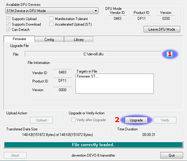
If your transmitter has been connected correctly ‘STM Device in DFU Mode’ will be displayed under ‘Available DFU Devices’. Otherwise this field will remain blank.
- Press the ‘…’ button and select the deviation-devoXX-vx.y.z.dfu file to install.
- Select ‘Upgrade‘ to install the firmware. This will be grayed-out if your transmitter is not detected. Do NOT use ‘Upload’ as this will destroy the dfu file on your PC.
Turn off the transmitter, and turn back on while holding ‘ENT’. There should be a USB logo on the screen. If this is a first-time install of Deviation, the PC should prompt to format a drive. Format using default options. Next, upgrade the file system via USB.
2.3 Upgrading the file system via USB
On the Devo F7 and F12E, do not enable USB mode, as the file system cannot be accessed from the desktop, and you need to use the ‘File Manager’ tab on the ‘Deviation Uploader’ to manage files. If you enable it, all you can do is format the drive, which will destroy your installation.
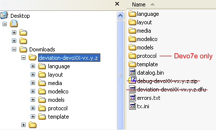
Open the folder that has been extracted from the zip file and copy all the files and directories inside this folder to the root of the transmitter USB drive. For details of the file-system please see 2.9 USB & File-system. The files with the extension ‘zip’, and ‘dfu’ need not to be copied.
If you are upgrading from an older release, don’t upgrade the ‘tx.ini’, and ‘hardware.ini’ files or the ‘models’ directory. Optionally, copy the ‘models’ directory to the transmitter except for the currently configured model files. This last step will ensure that the defaults for newly created models have the latest options set. If the ‘tx.ini’ file is overwritten, the stick calibration must be repeated and any settings reset.
2.4 DFU Installation with Deviation Uploader
The ‘Deviation Uploader’ is a Java (jar) file. You can either pass the jar file to the Java executable on the command line, or open the file in the GUI, using the Java application to open it. You will need to install Java from http://www.java.com/ if you haven’t already installed it.
Once the ‘Deviation Uploader’ is open, connect your transmitter to a USB port, and then turn it on while holding down the ‘EXT’ button.
If everything is working properly, you should see the ‘Transmitter’ change to the type of the connected transmitter. If it changes to the wrong transmitter type, stop now and seek help from the forums. If it doesn’t change, check the system information to see if the device is listed at all. If it shows up as an unknown device on Windows, then check your driver installation and try unplugging all other USB devices. Take the steps necessary to resolve any connection issues.
- Press the ‘…’ button and select the zip file for the firmware you will install. There is no need to unpack the zip file since the Deviation Uploader will handle that.
- If this is an initial install, all the ‘Replace’ boxes, along with ‘Format’ will be preselected. On the Devo F7 and Devo F12E initial install, select the ‘Format’ check box if not already selected.
- Click the ‘Install/Upgrade’ option. Installation will take a few minutes, so be patient. A pop-up dialog box will notify you when installation is completed. You are done.
- Turn off your Devo transmitter. When you turn it on again, you’ll be greeted by the Deviation splash screen.
On the F7 and F12E, do not enable USB mode, as the file system cannot be accessed from the desktop, and you need to use the ‘File Manager’ tab on the ‘Deviation Uploader’ to manage files.
For transmitters other than the F7 and F12E, turn the transmitter back on while holding ‘ENT’. There should be a USB logo on the screen. If this is a first-time install of Deviation, your computer may prompt to format a drive. Format using default options.
2.5 Upgrading the file system with ‘Deviation Uploader’
The Devo F7 and F12E do not support access via USB. Do not turn it on, as formatting the disk from your desktop will destroy your deviation installation.
If you followed the foregoing instructions for installing the deviation firmware ZIP file for your Devo using the Deviation Uploader tool, your installation is complete and no further installations are necessary. If, on the other hand, you unzipped the file and installed the firmware dfu file alone, then your must continue by installing the library dfu file from the same location. There is no advantage in doing the installation this way, but it can be done.
2.6 Deviation 5.0
The long-awaited firmware update from version 4.0.1 to version 5.0 was accomplished on April 30, 2016 and was announce on the DeviationTx website forum. Deviation version 5.0 is the current version and it includes all patches, bug fixes, improvements and protocols of the previous version. Even so, development continues, so new controllers will be added to the support list as well as new protocols and features, when they become available.
2.7 Nightly Deviation Builds
The Nightly builds are versions of Deviation with additional features beyond the Deviation 5.0 release version. The Nightly builds are provided to allow the Deviation community to fully exercise new features so the community can provide feedback and suggestions for improvement. As a user, you recognize that Deviation is a community supported software system, and members of this community can contribute by verifying, validating or commenting on the features that they’ve used. Nightly builds are found at http://www.deviationtx.com/downloads-new/category/13-nightly-builds
These builds are published when new features are added to the Deviation core feature set, when major bugs are corrected and when new hardware support is added. The nightly builds are tested but not to the rigorous extent of a full release. Please read this post! http://www.deviationtx.com/forum/5-news-announcements/1416-nightly-builds
The ONLINE User Manual for Deviation is regularly reviewed and updated to include information about new common features. Additionally, while best efforts are made by the Deviation community to update these User Guides, this documentation MAY NOT fully describe the features of the nightly builds. Any Deviation user with an update or change to the manual can submit additions and changes via the Deviation Bug Tracker at http://deviationtx.com/mantisbt
So should you load the Deviation 5.0 release or should you load a Nightly? Your own requirements will determine the answer to that question. If you use Walkera, Spectrum and Flysky models, and any number of variations of the WLToys V2x2 quads, the Deviation 5.0 release will be sufficient. If you have one of many newer small quads, or if you want support for additional hardware beyond additional transmitter modules, you should consider using the Nightly build.
If you are also adding hardware modifications, such as switches or transmitter modules, you should install the Deviation Nightly build first and review the available features. After Deviation is running, install your hardware and modify any settings to support your modifications. This helps you determine the source of issues later for troubleshooting.
2.8 Test Builds
Test Builds are for experienced users only. The Deviation Test builds are prepared by software developers to test new features or hardware options, and require a higher level of experience. These builds may also require specific transmitter configuration or hardware mods.
Some test builds require that you install the latest Nightly prior to installation. DO NOT INSTALL A TEST BUILD until you read the thread detailing the reason for that build and how to use it, and know why you would want to use it.
Once you install a test build, do add a post to the appropriate thread letting the developer know how things went! That’s why they are created - so developers can get feedback, even if it’s only a note that things worked fine.
2.9 USB & File-system
Deviation stores all configuration, bitmaps, and models as regular files on the USB file-system. USB can be most easily enabled by holding down the ‘ENT’ button while powering up the transmitter. Files can then be easily copied to or from the transmitter.
The directory structure is as follows:
| \tx.ini | Transmitter configuration. Includes trim settings, calibration data, and the last-used model number |
| \hardware.ini | Transmitter hardware setup, describing supported hardware modifications. number |
| \errors.txt | If the firmware crashes or reboots, debug information will be stored in this file |
| \datalog.bin | File for telemetry data |
| \media\config.ini | The color scheme and fonts for the transmitter |
| \media\sound.ini | Contains notes to play for various alarms |
| \media\*.bmp | Images used for the current transmitter theme |
| \media\*.fon | Font files |
| \models\default.ini | The default model, loaded whenever a model is cleared |
| \models\model*.ini | Configuration files for each model. Due to a limitation in the firmware, deviation cannot create new files. It is therefore necessary to have a modelxx.ini for each model regardless of whether it is currently in use. |
| \modelico\*.bmp | All available model icons (96x96 pixels is recommended but not required). Model icons must be saved as 16-bit BMP files in either RGB565 (non-transparent) or ARGB1555 (transparent) format. |
| \templates\*.ini | Configuration files used when loading predefined templates. These are nearly identical to the model configuration files, however they do not necessarily define all parameters |
| \language\lang*.* | Language translation files. These are UTF-8 text files containing the English string and the respective translated string. |
Note: Deviation only supports 8.3 style file names. That means file names should be no larger than ‘xxxxxxxx.yyy’**
3 Reporting Bugs
Nobody is perfect.
This firmware has been developed carefully and has been successfully tested by many users around the world. Nevertheless under some circumstances it could happen that the transmitter does not work as you expect. Sometimes this behavior will be a handling problem and sometimes a real bug. Do not hesitate to ask the community at http://www.deviationtx.com/forum. Please bear in mind that the firmware can only improved with your help.
If you find a bug in Deviation, please report it here: http://www.deviationtx.com/mantisbt
You will need to register for an account on the Deviation forums to submit a bug. That account will also allow you to communicate with the Deviation community, and will enable you to get email updates when the bug is updated/fixed.
Please provide as much information as possible in your ticket. Include:
- Build version (you can find this on the ‘USB’ page of the transmitter)
- Did you compile yourself, or download the dfu?
- Type of transmitter (Devo8, Devo7e, Devo8-emulator,...)
- Have you tried reproducing this on the emulator?
- Is this easily reproducible? If so, please provide step-by-step instructions
- What protocol are you using?
- If your transmitter rebooted, please provide the errors.txt on the root file-system of the transmitter along with the ‘debug-devo???.zip file that came with the dfu
The more detail you can provide, the faster fixing the issue will be.
4 A Note About this Manual
The images in this manual will generally show the Devo7e/10/12E interface. In some cases the Devo7e may not support a given feature or the screen may be slightly different. Situations where the Devo7e, 10, or 12E behave differently will be noted accordingly.
5 Main Page
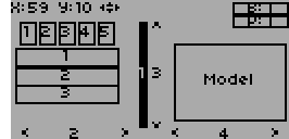
The standard main page layout is as follows:

Current Model: The name of the current model. Clicking the label will open up the Model Load page. The model is configured from section 9.1 Model setup (Std & Adv GUI).
Battery Voltage: Numerical representation of current transmitter battery state.
Transmitter Power: This indicates the currently selected transmitter power. It is configured from section 9.1 Model setup (Std & Adv GUI).
Model Icon: An image representing the current model. It is configured from section 9.1 Model setup (Std & Adv GUI).
Trims: The trim display can be configured to show up to 10 different horizontal and vertical trims.
Displays: These items can be text-boxes containing input, channel, telemetry, or timer data; bar graphs displaying channel data; or icons / toggles displaying specific states (ex. gear, flaps,…).
Quick Menus: Quick menus can be reached via a long UP/DN press. They can be defined from section 9.7 Main page config (Std & Adv GUI).
5.1 Safety System

Deviation has a safety system to prevent starting up in a dangerous state (for instance spinning up the main rotor of a helicopter accidentally). The safety system works by verifying that specific conditions are met before starting to transmit to the model. By default the output channel associated with the throttle stick must be minimum. The Deviation firmware does not include a mechanism to define new safety conditions, however, they can be added by directly modifying the model.ini file. While the safety message is displayed, the transmitter will not communicate with the model. This message may appear either when initially turning on the transmitter, or when switching to a different model. The message will disappear automatically once all safety conditions have been met or when ‘OK’ is pressed. In either case, Deviation will start communication with the model once the dialog is dismissed.
The safety values are in the ‘[safety]’ section, and the default looks like this:
[safety]
Auto=min
The ‘Auto’ value can also be any channel or input name, ‘Ch1’, etc. The ‘Auto’ tries to guess your throttle channel number. If that isn’t working, and you’re getting an unwanted warning, then changing it to ‘Ch1’ (DSMx protocols) or ‘CH3’ (most other protocols) will fix the problem. The ‘min’ value can also be ‘max’ or ‘zero’, to test that the channel or stick is at the maximum value and 0.
6 Navigating
The transmitter menus can be navigated via the physical buttons UP, D(ow)N, L(eft), R(ight), ENT(er), EX(i)T. All buttons and switches have been marked with the same descriptions as used in this manual.
There are several GUI elements that are used to configure settings on the transmitter
Buttons: Buttons can be selected to either toggle a setting or to enter a new menu.
Spin-Boxes: Spin-boxes are used to select one of multiple values.
There are two types of spin-boxes available:
- Spin-boxes consisting of both arrows and a 3d button may act both as spin-boxes (for selecting a value) and as a button (which can have various effects).
- Spin-boxes that contain only arrows and a white label do not act as buttons, and are only used for value selection.
Note that a spin-box may change between being selectable or not for different values of the spin-box.
The main menu is accessed by pressing ‘ENT’ on the main menu.

6.1 Navigating
- On all menu pages, ‘UP’ and ‘DN’ are used to navigate to the previous/next item.
- The ‘R+’ and ‘L-’ buttons are used on spin-box widgets to increase or decrease the selected value. In some cases holding down the button will use larger step values to move more quickly to the desired value.
- For buttons and rounded-spin-boxes, pressing ‘ENT’ will press the button,
- Pressing ‘EXT’ will remove selection form the current item. A long-press of ‘EXT’ will exit one (1) menu level.
7 Main Menu
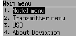
The main menu selections of the Deviation firmware are accessed by momentarily pressing the ENT button on the bottom right of the transmitter. The main menu consists of the following four options: Model menu, Transmitter menu, USB and About Deviation.
All settings which pertain to the usage of your Devention transmitter are accessed from the main menu. They include model options, language selection, display options, buzzer, vibration, stick mode, calibration, USB connectivity as well as version information.
7.3 USB
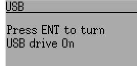
The USB page can be accessed by selecting ‘USB’ from the main menu. USB mode can then be toggled on/off to enable access to the transmitter’s file-system from a USB equipped computer. In this mode the file system of Deviation is accessible as a mass storage device. This will allow you to move files back and forth between the Deviation file-system and a PC. All configuration files are accessible in this mode.
NOTE: Entering USB mode should never be done while the model is bound, USB usage will disrupt signal transmission!
7.4 About Deviation
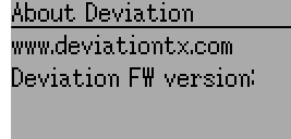
The Deviation release version can be accessed by selecting ‘About Deviation’ from the main menu.
8 Transmitter Menu
8.1 Transmitter config
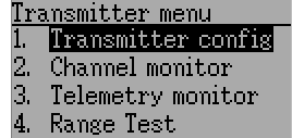
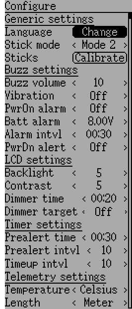
The configuration page defines various transmitter functions. It is entered from the main menu via ‘Transmitter menu’ followed by ‘Transmitter config’. Please note that all screens in this section show the Deviation default settings.
8.1.1 Generic settings
NOTE: This feature is not available for Devo7e.
Stick mode: Select one of Mode 1-4.
- Mode 1 is common in Europe. Elevator and Rudder on left, Throttle and Aileron on right.
- Mode 2 is common in North America. Throttle and Rudder on left, Elevator and Aileron on right.
- Mode 3 has Elevator and Aileron on left, Throttle and Rudder on right
- Mode 4 has Throttle and Aileron on left, Elevator and Rudder on right
Sticks: Calibrate the range of all analog sticks and dials.
To perform a stick calibration, highlight the Calibrate option and press the ENT button. Follow the on screen prompts for moving the sticks and confirming with the ENT button.
8.1.2 Buzzer settings
Power On alarm: Select the interval to be notified if your transmitter is on without action. Range is 0 – 60 minutes in 1 minute intervals.
Battery alarm: Set battery voltage at which alarm will sound. The voltage range is 3.30V – 12.00V in 0.01V increments.
Alarm interval: Set frequency of alarm when battery is low. Alarm intervals can be set from 5 seconds to 1 minute in 5 second intervals. It may also be set to Off.
Buzz volume: Set buzzer volume. Available range is 1 – 10; the buzzer may also be set to None.
Vibration: Enable vibration on alarms, if available.
Power-down alert: Play sound at power-down.
8.1.3 LCD settings
Backlight: Set screen brightness. Acceptable entries are from 1 to 10. It may also be turned off.
Contrast: Set screen contrast. Acceptable entries are from 1 to 10. .. if:: devo10 It may also be turned off.
Dimmer time: Set delay before screen dimming. Times may be set from 5 seconds to 2 minutes in 5 second intervals. A setting of Off will force backlight to remain on as long as the transmitter is on.
Dimmer target: Set screen brightness when dimmed. Acceptable entries are from 1 to 10 and may also be turned off.
8.1.4 Timer settings
Prealert time: Time before timer reaches zero to start beeping. Acceptable entries are from 5 seconds to 1 minute in 5 second intervals and may also be turned off.
Prealert intvl: How often to beep before timer reaches zero. Interval may be set from 1 – 60 seconds and may also be turned off.
Timeup intvl: How often to beep once timer has expired. Interval may be set from 1 – 60 seconds and may also be turned off.
8.1.5 Telemetry settings
Temperature: Set units to display temperature for telemetry. Available options are Celsius and Fahrenheit.
Length: Set units to display length for telemetry. Selection choices are Meters and Feet.
8.2 Channel monitor
The channel monitor screen allows the user to see the values of each channel as output by the transmitter. Channels without mixers will not be displayed. Channel output displayed is the value based on minimum / maximum values as well as scaling.
Example: A channel scaled from -60 to +60 will only display the range of values from -60 to +60 depending on the stick position.
8.3 Input Monitor
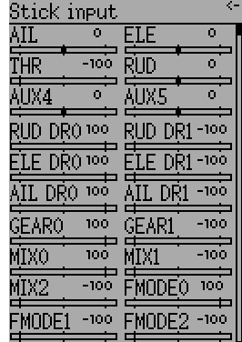
The input monitor screen shows the values associated with the current position of the control points. The values shown are a percentage of the total range of the controls based on a -100% to +100% scale.
NOTE: Devo7e is limited to AIL, ELE, THR, RUD, HOLD0, HOLD1, FMOD0 and FMOD1.
8.4 Telemetry monitor
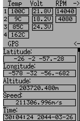
Certain protocols have the ability to transmit telemetry data back to the transmitter during use. Telemetry data may include, but is not restricted to, temperature readings, various voltage readings, motor or engine rpm, as well as GPS related information.
Telemetry data is turned off by default for all supported protocols except DEVO and FrSky. See the corresponding 9 Protocols section to learn which protocols support telemetry, and identify which fields will be available.
Since each protocol differs in the type of data it can return please see the original equipment manufacturers documentation concerning what additional hardware may be needed to collect this data.
Until valid data is transmitted the values will all be inverted

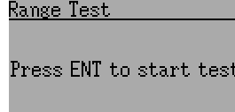
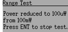
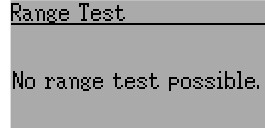
8.5 Range Test
It is recommended that you range test a new model before flying it the first time to verify that you will be able to control the model at normal flying distances. At some clubs, this is required as a safety measure. The range test page allows this. Once the range test page is opened, press the ‘Start test’ button to start the range test. The old and new power levels will be displayed. The standard procedure is then to walk about 30 meters away, and verify that you still have control of the aircraft. You can then press the ‘Stop test’ button to end the range test and restore the configured radio power level. Pressing the ‘Ext’ button to exit the page will also restore the power level. The radio range will be reduced by the square root of the change in power level. So going from 100mW to 100uW represents a change of power of roughly 1000, or a range reduction of a factor of a little over 30. So the normal range test of 30 meters would indicate that you should be able to control the model out to 900 meters. The installed RF module used for the current model must have a PA. If that is not the case, or the power level chosen for the model is already at the minimum value, a message to that effect will be displayed. |
|
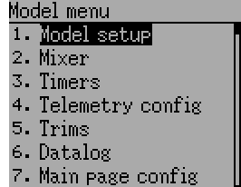
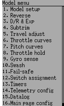
9 Model menu
The model menu allows selection, editing model configuration, alarms, logging and screen configurations. You can access the menu by pressing the ENT key to select the ‘Main menu’ and then again on ‘Model menu’.
Depending on the selection you have done for the Mixer GUI in section 9.1 Model setup (Std & Adv GUI), the model menu operation will be completely different.
The Advanced ‘2. Mixer’ page (9.2 Mixer (Adv GUI)) provides all of the functionality (and more) of the Standard Model.
| Advanced Model Menu | Standard Model Menu | ||
|
|
Note: The Advanced Mixer GUI is the default setting for all new models.
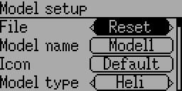
9.1 Model setup (Std & Adv GUI)
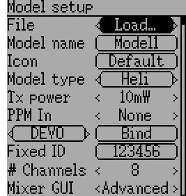
The model page provides various model configuration options.
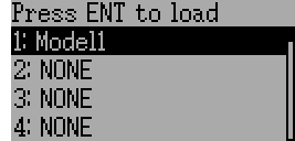
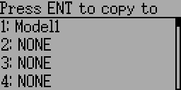
File: The File spin-box allows loading a new model, copying the existing model to a new location, resetting the current model to the default (all configuration is lost), and loading templates (see 9.1.1 Predefined Model Templates). Note that changing models may result in a safety message being displayed (see 5.1 Safety System).
|
|
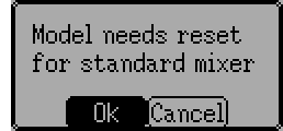
Mixer GUI: Defines which graphical user interface (GUI) to use for this model. The ‘Advanced’ GUI is the default for Deviation. The ‘Standard’ GUI is only available for Helicopter models and more closely resembles the stock GUI.
Standard mixer gui is designed for collective pitch helicopters with a flybar. It includes features spefic to those that aren’t needed on other aircraft, and may be missing features needed to properly control other aircraft. A flybarless collective pitch helicopter might benefit from some of the features of the standard GUI, it doesn’t need them and may need those missing features. You are strongly encouraged to use advanced mixer for all aircraft but collective pitch helicopters.
Note: If you switch from advanced mixer to standard mixer all data may be lost. Your data will be preserved if you switch from standard mixer to advanced mixer.
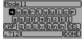
Model Name: Set the model’s name. Use the left, right, up, and down buttons then ENT to select each character.
Icon: Choose the model’s icon. Additional model icons can be installed (see 2.9 USB & File-system).
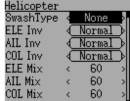
Model Type: Set the model-type available options are Heli, Plane and Multi. Helicopter models have an additional configuration page that can be accessed by clicking the Model type. The options for SwashType are identical to the ones in 9.8.5 Swash Configuration.
If you switch from model type Helicopter this will change the Mixer GUI to Advanced automatically because the Standard GUI only supports helicopters.
Transmitter Power: Specify the radio output power (when applicable). Available options are 100µW, 300µW, 1mW, 3mW, 10mW, 30mW, 100mW, 150mW.
Note: A stock Devo7e transmits with 7mW. Due to software configuration 150mW will always be displayed.
PPM In: Allows input from the DSC port primarily to control external hardware such as camera motors from a ‘head tracker’. Secondarily it may be used to enable the transmitter to act as a Master in a buddy-box setup. Available options are Channel, Stick and Extend.
The Stick and Channel modes are used for buddy-box setup and documentation can be found in chapter 11.1 Setting up a Buddy-Box. The Extend mode is used for FPV or external input setup and documentation can be found in chapter 11.2 Setting Up FPV or Other External Inputs.
Protocol: Set the type of receiver being used. Note that some protocols have additional options that can be accessed by pressing the Protocol spin-box when it is active. See section 10 Protocols for more on specific protocols. Note that a protocol change will disable any currently active protocol and will affect any active model. To enable the newly chosen protocol, use the Bind/Re-Init button described below.

Bind/Re-Init: Depending on the protocol and Fixed-ID setting, the transmitter may bind with the model on start-up, or may need to be manually bound once. See 10 Protocols for more on specific protocols. If the protocol does not support binding, the button will show ‘Re-Init’, which can be used to switch protocols without power-cycling the transmitter.
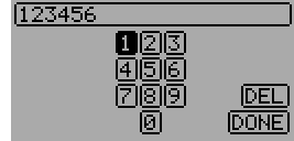
Fixed ID: The Fixed ID sets a unique code to ensure that the transmitter will only bind to a specific model. This is useful to ensure that the transmitter is not accidentally bound to the wrong model.
# Channels: Sets the number of channels to transmit (the maximum number of channels is dependent on the selected protocol).
9.1.1 Predefined Model Templates
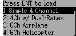
The Deviation firmware supports user-customizable predefined templates. By Selecting ‘Template...’ within the File spin-box from the Model page.
Additional templates can be added via USB to the ‘\template’ directory. A template does not completely replace your existing model, but instead only a portion of it. The currently supported templates will replace the mixer and trim definitions, but will not affect the display layout.
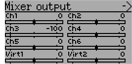
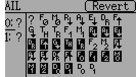
9.2 Mixer (Adv GUI)
The ‘Advanced’ GUI unleashes the full capabilities of the Deviation firmware, however it is unlike any commercial transmitter setup. Deviation also provides a more traditional setup interface for those who prefer it (see 9.8 Standard GUI Menu items). With the Advanced GUI, each output channel is composed of a series of one or more mixers each of which consists of a single input, an activation switch, and a function/curve that modifies the mixer output. This is a very powerful capability, but it will require learning a completely different method for setting up a model. To aid in quick setup, there are a few predefined configurations available (see 9.1.1 Predefined Model Templates), but to learn to modify and configure a model, read through this entire section carefully.
The Mixer page controls how inputs (sticks/switches) are assigned to output channels. The mixer page is accessed from the main menu by selecting the model icon..
The number of channels available is dependent on the number of channels selected in section 9.1 Model setup (Std & Adv GUI). Additionally there are 10 Virtual channels that can be used as an intermediate step for complex setups.
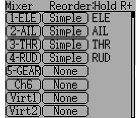
9.2.1 Channel Reorder
The Channel reorder page allows moving mixer definitions between channels as well as duplicating channel configurations. Note that the values displayed are the initial channel assignments. Whenever the page is loaded, the channels will be sequentially ordered representing the current state.
9.2.2 Channel configuration
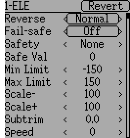
The Channel configuration provides the ability to configure the final channel outputs. Capabilities such as channel reverse and fail-safe values are applied here. Also available are controls for end-points, scaling, sub-trim, and a safety switch (which could be used to ensure that a motor cannot spin-up while working on a model)
Changes to this page will immediately effect the channel output. Pressing ‘Cancel‘ will restore the shown values to their last saved state.
Reverse: Reverse the direction of servo rotation
Fail-safe: Specifies a value that the receiver should use when it loses signal from the transmitter. The range is between -125 and +125 or None. Not all receivers support this capability.
Safety: Specifies a switch that will override all mixers and force the channel output to ‘Safe Val’ when flipped.
Safe Val: If a safety switch is chosen the Safe Val can also be specified. The acceptable range of Safe Val is any value between -150 and 150.
Min Limit/Max Limit: These values define the minimum and maximum values that the transmitter will ever send to the receiver (after all scaling, trims and mixer are applied). If a calculated value is outside the min/max range, it will be clipped to either the min or max value as appropriate. Default is -150 for Min Limit and +150 for Max Limit. Maximum setting is -250 to 0 for Min Limit and 0 to 250 for Max Limit.
Scale-/Scale+: These values define a final scalar to adjust the servo throw. Allowed entries are between 1 and 250. When you alternate Scale+ Scale- will be changed in the same way. If Scale- has been set to a different value than Scale+ both data will act separately until you set them to the same value again.
Subtrim: Adjust servo zero position. The available range is between -50.0 and +50.0 in 0.1 increments.
- Speed: Adjust maximum servo speed. Zero is disabled (fastest), Range is between 1 (slowest) and 250 (fastest). Servo speed is defined as number of degrees per 100msec (assuming a min/max throw of 120degrees).
- Example: A value of 60 will give a speed of 60degrees per 100msec which is equivalent to center-to max in 100msec. Most servos are rated at ~60degrees/0.1sec, so a speed > 60 will have no affect on most servos. A value of 30 should be approx twice as slow as a typical servo.
9.2.3 Virtual channel configuration
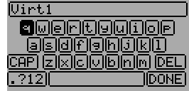
If you press ENT on a virtual channel a keyboard screen is shown where you may edit the default name. You can use L/R/UP/DN buttons followed by ‘ENT’ to select.
9.2.4 Simple Mix Type
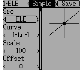
The Simple mix type is the simplest manner of defining a channel. It allows defining a primary-input (stick, switch, or other channel), and applying a curve or function to that input. The result can also be scaled or have an alternate zero-offset. You cannot use a toggle or switch to activate or deactivate this setup.
A ‘Long-ENT’ press will update the current mixer settings, making it possible to test them on the transmitter.
Src: The input source controlling this mixer.
Curve: The function applied to the input to generate the output. See section 9.2.9 Available Curves for more info. Depending on curve-type, pressing curve may display the curve editor (see 9.2.10 Curve Editing).
Scale: A multiplicative scalar that is applied after the Curve to control the output range.
Offset: An additive offset that is applied after the scaling.
9.2.5 Expo & Dual-Rate Mix Type
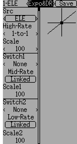
Selecting a value for Switch1 or Switch2 will activate the corresponding section. Each section can either have a ‘linked’ curve (curve is the same as the ‘High-Rate’ curve) in which case only the scalar can be modified, or alternatively can have an independent curve definition. Pressing the ‘Mid-Rate’ or ‘Low-Rate’ button for a given switch will toggle between linked and independent curves.
A ‘Long-ENT’ press will update the current mixer settings, making it possible to test them on the transmitter.
Src: The input source controlling this mixer.
Curve: The function applied to the input to generate the output. See section 9.2.9 Available Curves for more info. Depending on curve-type, pressing curve may display the curve editor (see 9.2.10 Curve Editing).
Switch1 or Switch2: Specify a switch to enable Medium or Low rates.
Scale: A multiplicative scalar that is applied after the Curve to control the output range.
9.2.6 Complex Mix Type
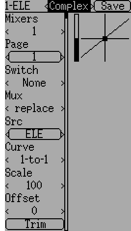
The Complex mix type unlocks the full power of the mixer system. For a given channel, any number of mixers can be applied to affect the final result. Each mixer is applied based on whether the specified switch is active, and can either replace, add to, or multiply to the previous mixers for this channel. Using this system it should be possible to define an output channel as a combination of any number of inputs.
A ‘Long-ENT’ press will update the current mixer settings, making it possible to test them on the transmitter.
The Complex Mixer page has the following options:
Mixers: Specify the number of mixers for this channel. If you increase the number a new mixer will be added after the last existing page.
Page: Specify the current mixer page being edited. Pressing the spin-box will allow reordering the pages of the current channel.
Switch: Specify an optional switch which determines whether the current mixer is active.
Mux: Defines how the current mixer is applied to the previously defined mixers for this channel. Options are:
- Replace: If this mixer is active, all previous mixers are ignored.
- Add: Add the value of this mixer to the previous mixers.
- Mult: Multiply the value of this mixer with the previous mixers. Note that the values are percentages, so multiplying by 50 actually multiplies by .5.
- Max: The output will be the greater of the current mixer vs the previous mixers.
- Min: The output will be the lesser of the current mixer vs the previous mixers.
- Delay: Delay the output of this mixer when used with a fixed curve. Scale of 100 represents 5 seconds delay. Can be varied by using scale or offset.
Src: The input source controlling this mixer.
Curve: The function applied to the input to generate the output. See section 9.2.9 Available Curves for more info. Depending on curve-type, pressing curve may display the curve editor (see 9.2.10 Curve Editing).
Scale: A multiplicative scalar that is applied after the Curve to control the output range.
Note that while the scale value is limited to 100%, the mixer may provide a value larger than 100% if an offset is set or if the trim value is non-zero.
Offset: an additive offset that is applied after the scaling.
Trim: Selects whether or not any trims for the selected source are applied to this mixer.
A given mixer can be considered to have the general form:
M(x) = if(Switch) { Src * Curve * Scale + Offset} else {0} + Trim
The combination of mixers for a given output channel is defined by the Mux type:
For a ‘Replace’ mux:
Cx = if(Switchn) {Mn} else if (Switchn-1) {Mn-1} … else if (Switch0) {M0}For a ‘Multiply’ mux:
Cx = if(Switchn) {Mn} else {1} * if (Switchn-1) {Mn-1} else {1} * … * if (Switch0) {M0} else {1}For an ‘Add’ mux:
Cx = if(Switchn) {Mn} else {0} + if (Switchn-1) {Mn-1} else {0} + … + if (Switch0) {M0} else {0}For a ‘Max’ mux:
Cx = MAX(if(Switchn) {Mn} else {0}, if (Switchn-1) {Mn-1} else {0}, …, if (Switch0) {M0} else {0})For a ‘Min’ mux:
Cx = MIN(if(Switchn) {Mn} else {0}, if (Switchn-1) {Mn-1} else {0}, …, if (Switch0) {M0} else {0})
9.2.7 Cyclic
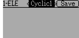
Cyclic1, Cyclic2, Cyclic3: The 3 outputs of the helicopter swash-plate mix. These will represent the 3 servos connected to the helicopter swash-plate (see 9.8.5 Swash Configuration).
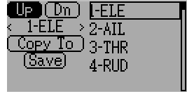
9.2.8 Reordering Mixers
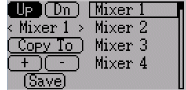
Select the respective mixer and use the up/down buttons to move the order of the selected mixer. Note that the mixer name represents its position when the reorder dialog was opened. If the dialog is closed and reopened, all mixers will be shown as numbered sequentially.
The reorder page can add new mixers or delete existing ones using the ‘+’ and ‘-’ buttons respectively. A mixer can also be copied to an existing mixer (overwriting it in the process) by using the ‘Copy To’ functionality.
9.2.9 Available Curves
The following curve functions are supported:
- 1-to-1: Output is equal to the input (not editable).
- Fixed: Output is constant regardless of input (offset editable).
- Min/Max: Output is -100 if input is less than the specified value and 100 otherwise.
- Zero/Max: Output is 0 if input is less than the specified value and 100 otherwise.
- >0: Output matches input when greater than the specified value, and 0 otherwise.
- <0: Output matches the input when less than the specified value, and0 otherwise.
- ABSVAL: Output is the absolute-value of the input (editing the specified value will alter how the absolute-value is applied)
- EXPO: Apply exponential curve to the input for non-linear response (editable see 9.2.10 Curve Editing).
- Deadband: Output will not respond to input values near zero (editable see 9.2.10 Curve Editing).
- Multi-point: Curve is based on 3, 5, 7, 9, 11 or 13 user-defined points (editable see 9.2.10 Curve Editing).
The default value for any of the offsets in above mentioned curves is 0 (zero). If you change the curve for one input the offset will be transferred to the new curve if possible.
9.2.10 Curve Editing
The Curve Editor is accessed by selecting the curve spin-box when it is selectable. The 1-1 and Fixed curve types may not be edited, and the curve-box will not be selectable if one of these curves is currently active.
The Curve editor page will be different depending on which curve is selected. It is not possible to change the curve type from the curve editor (except when a multi-point curve is selected). Values can be set using the spin-box or by touching the graph.
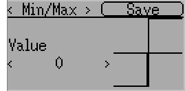
For the Min/Max, Zero/Max, >0, <0, and ABSVAL, the controls allow setting the transition point along the x-axis. A value of ‘0’ will be symmetric around the y-axis, positive or negative values will move the center point accordingly
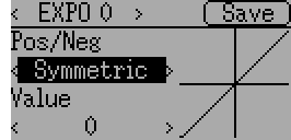
For the Expo curve, the controls allow independently configuring the shape of the curve for values greater-than or less-than zero.
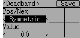
For the Deadband curve, the controls allow independently configuring the deadband width for values greater-than or less-than zero.
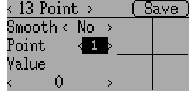
For the Multi-point curves, each point can be individually set. Points are set by choosing the point number and then choosing a value. The minimum number of points allowable is 3 the maximum number of points is 13. Enabling ‘Smooth’ will apply a smoothing function rather than connecting points via straight lines.
9.3 Timers (Std & Adv GUI)
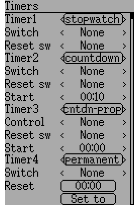
The timer page defines up to 4 available timers. Timers can count either up or down, and can be enabled either manually from the main screen or by an input trigger (stick or switch).
Available timers are stopwatch, countdown, stopwatch-proportional, countdown-proportional, and permanent.
Timers can also be optionally configured to be reset via an alternate switch (only when using the Advanced GUI).
Both proportional timers need an input between 0 and 100 to act correctly. If you use these timer for throttle a virtual mixer must be used as the input to scale -100 to 100 values into 0 to 100.
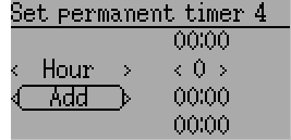
The ‘permanent’ timers are similar to an odometer and have their values saved in the model.ini file. They will maintain their previous value when powering up the transmitter. You can set the timer by using the ‘Set to’ button and reset by pressing the ‘Reset’ button.
9.4 Telemetry config (Std & Adv GUI)
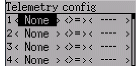
The telemetry configuration page allows specifying alarms when specific telemetry events occur.
- Telemetry: Specify the telemetry input to use for alarm control. The set of values available will depend on the protocol.
- Equality: Can be ‘>=’ or ‘<=’ indicating whether a value above or below the target causes an alarm.
- Target: The target value for the alarm.
9.5 Trims and Virtual Inputs (Std & Adv GUI)
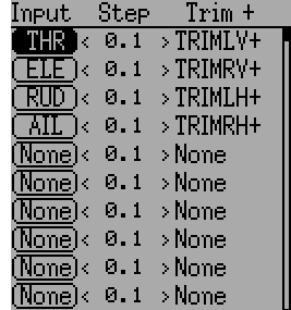
The trim page allows assigning the trim buttons and trim step, as well as configuring buttons to work as virtual inputs (see 11.3 Using a Trim as a Virtual Switch). It is accessed from the main menu via ‘Model menu’ followed by ‘Trims’.
If the ‘Input’ field is set to an input stick, then the trim can be applied as part of the mixer, and will operate as a typical trim control. If the ‘Input’ field is set as a channel or virtual-channel output, the value is applied directly to the channel output. In this case, the selected ‘Trim +’ and ‘Trim -’ buttons can operate as a virtual stick to control an output channel.
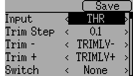
The trim-step defines how sensitive the trims are to input. The maximum number of trim steps is +/-100. So a step size of 0.1 will allow a full +/- 10% of trim adjustment on the servo.
The trim-step can be changed on the main screen. If you have to change the source also please use the dialog accessed by pressing the respective ‘Input’ button. Here you may also add a switch to the trim. If a switch is added to the trim, then it will have different trim values in each switch position.
9.6 Datalog (Std & Adv GUI)
Note: This feature is not available for Devo7e.
The Datalog feature allows storing a history of input or output positions as well as telemetry info over a period of time. This can be used to examine and replay a flight as well as to visualize telemetry information at a later time. Logs are persistent and Deviation will continue writing to the end of the previous log by default.
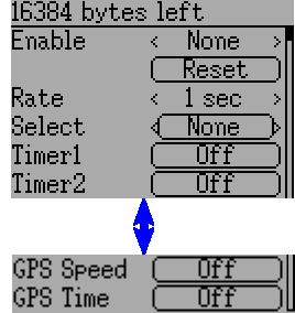
- # bytes left: Indicates how many bytes can be written to the log before it is full.
- Enable: Input which enables logging.
- Reset: Clear the current log.
- Rate: How often to write current info to the log file.
- Select: Quickly set or reset which items are logged.
- Controls: Following ‘Select’ are a list of all controls which may be logged. They include timers, inputs, outputs, and virtual channels, and Telemetry. The more items logged the faster the log will fill up.
Logging more information By default, the log can only store 16kB of data. You can increase the amount of data to be stored by changing the datalog.bin file on the transmitter to a larger size. Deviation cannot increase the size of this file, so its size indicates the maximum data that can be stored.
Note: This is a feature for advanced users only. There is currently no software provided to analyze the logs, and they cannot be visualized from within the transmitter. Please check the downloads section on www.deviationtx.com for conversion tools.
9.7 Main page config (Std & Adv GUI)
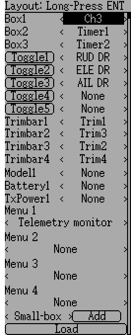
The main page config page is used to configure the main-page display. This page allows definition of which elements are shown on the main page.
The following types of objects can be displayed:
- Box: Display a numeric value. Values can be timers, channel values, stick inputs, etc. There are two types of boxes: big and small. The only difference is the size of the box and the text within it.
- Trimbar: Display a trim value. These generally are controlled by the trim switch and indicate what the current trim position is. There are two types of trims. V-Trims show a vertical bar, and H-Trims show a horizontal bar. After inserting all trims do have numbers only.
- Model (Icon): Display the icon related to the selected model.
- Battery: Display the battery voltage.
- TxPower: Displays the actual transmitter rating.
- Bargraph: Displays a vertical bar. The value of the bar is a channel output.
- Toggle: Show an icon indicating the state of a toggle switch. There can be 1, 2, or 3 icons defined for a given toggle indicating different states depending on the switch position. Two-state switches can have up to 2 icons. Three-state switches can have up to 3 icons.
- (Quick) Menus: Quick menus define quick-access pages that can be reached via a long UP/DN press.
9.7.1 Configuring object position
Note: This feature is not available for Devo7e.
Pressing and holding the ENT button from the model configuration page will switch to the object position screen. Each of the visual objects can be selected using the UP/DN buttons. Pressing ENT again will allow moving the placement of the selected object. The UP/DN/L/R buttons will move the selected object on the screen. Press EXT once to exit move mode, and again to go back to the main page config menu.
9.7.2 Creating Objects
Note: This feature is not available for Devo7e.
Select the object type from the spin-box on the left, then press ‘Add’ to create the object. This will add the relevant object type to the relevant section in the menu with a type of ‘None’ (where applicable). Then move the cursor to the newly created object and configure as desired.
9.7.3 Loading Objects
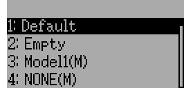
You can ‘Load’ alternate templates, to change the main page layout. If you select ‘Default’ the layout will be set to the standard layout as shown in section 5 Main Page.
Selecting ‘Empty’ will clear all objects. You may start from scratch.
If you want to use a layout from another model select the model whose layout you wish to use. The object positions (see 9.7.1 Configuring object position) will be transferred when selecting from an existing template or model. Templates based on existing models have an (M) designation within the file list.
Additionally these templates can be created in the emulator or downloaded from the forums or even done by manual edit of the modelxx.ini file.
9.7.4 Configuring Objects
- Box: Select timer, telemetry, channel, or input from scroll-box
- Trim: Select trim channel from scroll-box
- Model: Not configurable
- Battery: Not configurable
- TxPower: Not configurable
- Bargraph: Select channel from scroll box
- Toggle: Select channel or input from scroll-box. Press related ‘Toggle’ button to choose icon
- Menu: Choose page to display for each of 4 quick-page slots
You can delete any object but a Menu page by selecting the ‘Delete’ option and pressing the ‘ENT’ button.
9.7.5 Choosing toggle icons
Pressing the ‘Toggle’ button on a toggle object allows selecting the related icons. Channels, sticks, and 2-position sticks can have 2 icons. 3 position sticks (if any) can have 3 icons. Each of the 2 (or 3) icon states can be set to empty, defining that no icon is shown for this state. The Deviation firmware comes with several predefined icons to choose from.
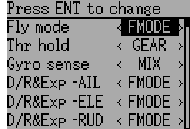
9.8 Standard GUI Menu items
The Standard GUI is an alternative interface from the Advanced GUI’. Which interface is used is chosen by the ‘Mixer GUI’ setting in section 9.1 Model setup (Std & Adv GUI). The Standard GUI is only available for Helicopter-type models at this time. The pages of the Standard GUI are as follows:
- Model setup: Model configuration page (See section 9.1 Model setup (Std & Adv GUI))
- Reverse: Servo reverse
- D/R & Exp: Dual-rates setup
- Subtrim: Servo sub-trim
- Travel adjust: Servo travel-adjust
- Throttle curves: Throttle curve setup
- Pitch curves: Pitch curve setup
- Throttle hold: Throttle-hold configuration
- Gyro sense: Gyro-sense configuration
- Swash: Swash Setup
- Fail safe: Fail-Safe configuration
- Switch assignment: Assign switch controls
- Timers: Timer configuration (See section 9.3 Timers (Std & Adv GUI))
- Telemetry config: Configure telemetry alarms (See section 9.4 Telemetry config (Std & Adv GUI))
- Datalog: Configure telemetry logging (See section 9.6 Datalog (Std & Adv GUI))
- Main page config: Configure main page display (See section 9.7 Main page config (Std & Adv GUI))
9.8.1 Servo Reverse
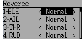
The servo reverse page allows quickly setting each channel to work in either normal or reversed mode. These settings are equivalent to the ‘Reverse’ setting on the Channel Configuration sub-page of the Mixer menu when using the Advanced GUI (see section 9.2.2 Channel configuration)
9.8.2 Dual-Rate/Expo setting
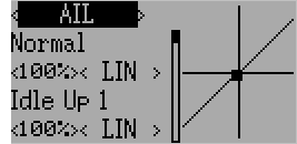
The dual-rate and expo page allows configuration of curves for the Aileron, Rudder, and Elevator channels. Up-to 3 rates can be configured for each channel, and either a scaled-linear or exponential curve can be selected for each. The number of settings depends on the switch assigned to the dual-rates function on the Switch Assignment page (see 9.8.9 Switch Assignment)
9.8.3 Sub-trim Adjustment
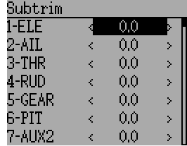
The sub-trim adjust page allows setting the zero-point of the servos for each channel. This is equivalent to the ‘Subtrim’ setting on the Channel Configuration sub-page of the Mixer menu when using the Advanced GUI (see 9.2.2 Channel configuration). Acceptable values range from -50 to +50 in 0.1 increments.
9.8.4 Servo Travel Adjust
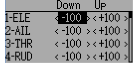
The servo-travel adjust page configures the maximum positive/negative travel of each servo. This is equivalent to the ‘Scale+’ and ‘Scale-’ settings on the Channel Configuration sub-page of the Mixer menu when using the Advanced GUI (see 9.2.2 Channel configuration). Acceptable values for Down are from -175 to -1 and Up values range from +1 to +175. The default values are -100 and +100 respectively.
9.8.5 Swash Configuration
The Swash configuration page configures the swash type. More information about swash-types can be found in section 11.4 Swash Mixing. The settings on this page are equivalent to those on the model configuration page (see 9.1 Model setup (Std & Adv GUI)), and configuration for both pages is provided below.

The available SwashType values are:
- None/1Servo: Used For FBL. Mixing occurs in receiver
- 120/3Servo 120: 120-degree swash
- 120x/3Servo 120x: 120 degrees swash (alternate config)
- 140/3Servo 140: 140 degree swash
- 90/3Servo 90: 90 degrees swash
The ELE Mix, AIL Mix, and PIT Mix are scaling factors applied to the input sticks before mixing is done. These can be used to adjust for different linkage lengths or different servo throws. The allowed range is -100 to 100 with a default of 60. Note that setting these values too large can result in too much servo throw and make the model unresponsive to stick control.
9.8.6 Throttle Curve

The throttle curve page allows defining a piece-wise linear curve for the throttle channel. Different curves can be selected for each flight-mode. Each point value can be enabled to be interpolated from the points surrounding it.
9.8.7 Pitch Curve

The pitch curve allows defining a piece-wise linear curve for the collective/pitch channel. Different curves can be selected for each flight-mode as well as for throttle-hold. Each point value can be enabled to be interpolated from the points surrounding it.
9.8.8 Gyro Sensitivity
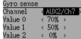
The gyro-sensitivity page enables configuring up-to 3 sensitivity values for the gyro as well as which channel to use for sending the gyro value. Acceptable values range from 0 to 100%.
9.8.9 Switch Assignment
The switch assignment page enables configuring which switches to use for each capability in the standard-GUI. The same switch may be assigned to multiple capabilities.
9.8.10 Throttle Hold
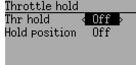
The throttle-hold page is used to enable/disable the throttle-hold capability. Specifying ‘Hold position’ defines the throttle value when the Throttle-hold switch is set. Hold position can be set from -200 to 200.
9.8.11 Fail-Safe Configuration
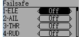
The fail-safe page is used to configure the fail-safe value for each channel (if the protocol supports this feature)
10 Protocols
Some protocols have additional customization or limits. Each of the protocols is described below. An asterisk (‘*’) before the protocol name in the section header means a hardware module must be added to the transmitter to support the protocol. On the transmitter display the asterisk means Deviation does not detect the required module (not installed, hardware.ini not correct, or other issue communicating with the module.) More information can be found in the Module installation guide:
https://bitbucket.org/PhracturedBlue/deviation/wiki/ModuleInstallation
10.1 Protocol: DEVO
The DEVO protocol is used to maintain compatibility with the Walkera DEVO receivers/models. This protocol supports up to 12 channels. The DEVO protocol supports both auto-binding and manual-binding. If Fixed ID is set to ‘None’ the transmitter will attempt to auto-bind with the receiver every time it is powered on. If a value is set for Fixed ID, the receiver must be bound manually one-time using the ‘Bind’ button, after which it should stay bound. Note that the Fixed ID is only part of the binding procedure. Two transmitters with the Same ID cannot control the same model.
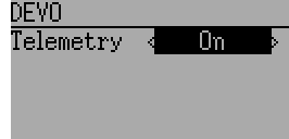
The DEVO protocol also supports enabling/disabling the telemetry capability. This option is accessed by pressing the Protocol spin-box when DEVO is shown.
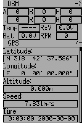
The following fields are available in Devo Telemetry. Note that not all models/receivers report all fields, and that some fields require extra modules to enable.

- Temp1/2/3/4: Temperature readings. These can be battery, motor, or ambient values
- Volt1/2/3: Voltage readings for receiver battery, and external batteries
- RPM1/2: Motor/Engine RPM values
- GPS Data: Current position, speed and altitude from GPS module
10.2 Protocol: WK2801
The WK2801 protocol is used to control older Walkera models. The previous Walkera models were segmented into 3 similar but not identical protocols: WK2801, WK2601, WK2401. This roughly corresponds to the number of channels supported, but many of the newer 6-channel receivers actually support the WK2801 protocol. It is recommended to try the WK2801 protocol 1st when working with older Walkera models before attempting the WK2601 or WK2401 mode, as the WK2801 is a superior protocol. The WK2801 protocol supports up to 8 channels, and both auto-binding and manual-binding. If Fixed ID is set to ‘None’ the transmitter will attempt to auto-bind with the receiver every time it is powered on. If a value is set for Fixed ID, the receiver must be bound manually one-time using the ‘Bind’ button, after which it should stay bound.
10.3 Protocol: WK2601
The WK2601 protocol is used to control older Walkera models. The previous Walkera models were segmented into 3 similar but not identical protocols: WK2801, WK2601, WK2401. This roughly corresponds to the number of channels supported, but many of the newer 6-channel receivers actually support the WK2801 protocol. It is recommended to try the WK2801 protocol 1st when working with older Walkera models before attempting the WK2601 or WK2401 mode, as the WK2801 is a superior protocol. The WK2601 protocol supports up to 7 channels, and only supports auto-binding. The fixed ID can be used, but does not prevent auto-binding during power-on.
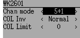
The WK2601 protocol also supports additional options. These are accessed by pressing the Protocol spin-box when Wk2601 is shown:
Chan mode: Sets how channels are processed:
- 5+1: AIL, ELE, THR, RUD, GYRO (ch 7) are proportional. Gear (ch 5) is binary. Ch 6 is disabled
- Heli: AIL, ELE, THR, RUD, GYRO are proportional. Gear (ch 5) is binary. COL (ch 6) is linked to Thr. If Ch6 >= 0, the receiver will apply a 3D curve to the Thr. If Ch6 < 0, the receiver will apply normal curves to the Thr. The value of Ch6 defines the ratio of COL to THR.
- 6+1: AIL, ELE, THR, RUD, COL (ch 6), GYRO (ch 7) are proportional. Gear (ch 5) is binary. This mode is highly experimental.
- COL Inv: Invert COL servo
- COL Limit: Set maximum range of COL servo
10.4 Protocol: WK2401
The WK2401 protocol is used to control older Walkera models. The previous Walkera models were segmented into 3 similar but not identical protocols: WK2801, WK2601, WK2401. This roughly corresponds to the number of channels supported, but many of the newer 6-channel receivers actually support the WK2801 protocol. It is recommended to try the WK2801 protocol 1st when working with older Walkera models before attempting the WK2601 or WK2401 mode, as the WK2801 is a superior protocol. The WK2401 protocol supports up to 4 channels, and only supports auto-binding. The fixed ID can be used, but does not prevent auto-binding during power-on.
10.5 Protocol: DSM2
The DSM2 protocol is used to control many Spektrum™ and JR™, as well as other models using this protocol. While the DSM2 protocol can support up to 14 channels, Deviation is currently limited to a maximum of 12. Note that many receivers with less than 8 channels require the Transmitter to send 7 or fewer channels. Make sure the # of channels is set appropriately for the receiver. DSM2 does not support auto-binding. If Fixed ID is set to None, a transmitter-specific ID is used instead. It is necessary to manually bind each model before the first use.
Note that binding does not exit until you move the AIL or ELE controls. This is so you can press the Failsafe button on some DSM receivers to set the failsafe value.

The DSM2 protocol also supports enabling/disabling the telemetry capability. This option is accessed by pressing the Protocol spin-box when DSM2 is shown.
The following fields are available in DSM2 Telemetry. Note that a dedicated telemetry module and additional sensors are needed to capture this data
- FadesA/B/L/R: The number of times each antenna has received a weak signal. Ideally these numbers should all be similar, indicating even reception to each antenna
- Loss: The number of times complete signal loss (dropped frame) occurred
- Holds: The number of times the receiver entered fail-safe mode due to loss of signal
- Volt1/2: Battery voltage for receiver and an external source
- RPM: Engine/Motor speed
- Temp: Temperature from external temperature sensor
- GPS Data: Current position, speed and altitude from GPS module
10.6 Protocol: DSMX
The DSMX protocol is used to control many Spektrum™ and JR™, as well as other models using this protocol. While the DSMX protocol can support up to 14 channels, Deviation is currently limited to a maximum of 12. Note that many receivers with less than 8 channels require the Transmitter to send 7 or less channels. Make sure the # of channels is set appropriately for the receiver. DSMX does not support auto-binding. If Fixed ID is set to None, a transmitter-specific ID is used instead. It is necessary to manually bind each model before the first use.
Note that binding does not exit until you move the AIL or ELE controls. This is so you can press the Failsafe button on some DSM receivers to set the failsafe value.
Note that unlike Spektrum™ or JR™ transmitters, Deviation will not automatically select between DSM2 and DSMX. The user must select which protocol to use.

The DSMX protocol also supports enabling/disabling the telemetry capability. This option is accessed by pressing the Protocol spin-box when DSMX is shown.
The list of DSMX telemetry fields is identical to those in the DSM2 Protocol, and are documented in section 10.5 Protocol: DSM2.
10.7 Protocol: J6Pro
The J6Pro protocol is used to support Nine Eagles™ models. Only models compatible with the J6Pro transmitter can be used. Many older 4-channel Nine Eagles models used a different protocol that is unsupported. The J6Pro protocol supports up to 12 channels, although only models with 6 channels have been tested. J6Pro does not support auto-binding. If Fixed ID is set to None, a transmitter-specific ID is used instead. It is necessary to manually bind each model before the first use.
10.8 Protocol: *Flysky
The Flysky protocol is used to control Turnigy/Flysky receivers as well as a few other models using the same protocol (WL V911, Xieda 9958, etc). NOTE: This protocol requires the addition of an ‘A7105’ hardware module to function. See the following document for more information:
https://bitbucket.org/PhracturedBlue/deviation/wiki/ModuleInstallation
The Flysky protocol supports up to 12 channels, and both auto-binding and manual-binding. If Fixed ID is set to ‘None’ the transmitter will attempt to auto-bind with the receiver every time it is powered on. If a value is set for Fixed ID, the receiver must be bound manually one-time using the ‘Bind’ button, after which it should stay bound.
The Flysky protocol also supports WLToys extensions to the protocol. These are accessed by pressing the Protocol spin-box when Flysky is shown:
V9x9: Enables the extensions for the WLToys V939, V949, V959, v969, etc quadcopters.
- Lights are controlled by Channel 5
- Video is controlled by Channel 6
- Camera is controlled by Channel 7
- Flip is controlled by Channel 8
V6x6: Enables the extensions for the WLToys V636 and V686 quadcopters.
- Lights are controlled by Channel 5
- Flip is controlled by Channel 6
- Camera is controlled by Channel 7
- Video is controlled by Channel 8
- Headless mode is controlled by Channel 9
- RTH mode is controlled by Channel 10
- X and Y calibration are controlled by channels 11 and 12, respectively.
V912: Enables the extensions for the V912, V913 and V915 helicopters
Note that if these channels are assigned to a switch, turning the switch on toggles the state, and turning the switch off has no effect. Thus to turn the lights on, flip the switch assigned to Channel 5 from off to on. Flipping the switch back to off has no effect. Flipping the switch back on now turns the lights back off.
10.9 Protocol: *Hubsan4
The Hubsan4 protocol supports the Hubsan-X4 quadracopter and the Estes Proto X (but not the Proto X SLT). No other models have been tested with this protocol. NOTE: This protocol requires the addition of an ‘A7105’ hardware module to function. See the following document for more information:
https://bitbucket.org/PhracturedBlue/deviation/wiki/ModuleInstallation
The Hubsan4 protocol supports up to 7 channels, and only supports auto-binding. The fixed ID can be used, but does not prevent auto-binding during power-on. The 1 st 4 channels represent Aileron, Elevator, Throttle, and Rudder. Additional channels control the quadracopter special functions:
- Channel 5 controls the LEDs
- Channel 6 enables ‘flip’ mode
- Channel 7 Turns video on/off
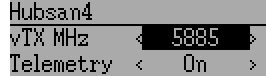
Options configurable on the Hubsan page:
- vTX MHz: Defines the frequency used by the Hubsan H107D video transmitter (Requires a 5.8GHz receiver capable of receiving and displaying video).
- Telemetry: Enable receiving of model battery voltage.
10.10 Protocol: *Joysway
The Joysway protocol supports the Joysway Caribbean model yacht, and the J4C12R receiver used in the Joysway Orion, Explorer, Dragon Force 65 model yachts and Force2 60 model catamaran. No other models or receivers have been tested with this protocol, including air versions of the J4C12R. NOTE: This protocol requires the addition of an ‘A7105’ hardware module to function. See the following document for more information:
https://bitbucket.org/PhracturedBlue/deviation/wiki/ModuleInstallation
The Joysway protocol supports up to four channels, does not support auto-binding, but will bind whenever a receiver requests binding. If Fixed ID is set to None, a transmitter-specific ID is used instead. It is necessary to bind each model before the first use.
The first channel normally controls the sheets and the second channel the rudder, but this may vary from model to model.
10.11 Protocol: *Frsky-V8
The Frsky-V8 protocol is used to control older Frsky™ receivers using the one-way protocol. NOTE: This protocol requires the addition of an ‘CC2500’ hardware module to function. See the following document for more information:
https://bitbucket.org/PhracturedBlue/deviation/wiki/ModuleInstallation
The Frsky-V8 protocol supports 8 channels, does not support auto-binding. If Fixed ID is set to None, a transmitter-specific ID is used instead. It is necessary to manually bind each model before the first use.
10.12 Protocol: *Frsky
The Frsky protocol is used to control newer (telemetry enabled) Frsky™ receivers using the two-way protocol. NOTE: This protocol requires the addition of an ‘CC2500’ hardware module to function. See the following document for more information:
https://bitbucket.org/PhracturedBlue/deviation/wiki/ModuleInstallation
The Frsky protocol supports up to 8 channels, does not support auto-binding. If Fixed ID is set to None, a transmitter-specific ID is used instead. It is necessary to manually bind each model before the first use.
The Frsky2way protocol also supports enabling/disabling the telemetry capability. This option is accessed by pressing the Protocol spin-box when Frsky2way is shown.
10.13 Protocol: *Skyartec
The Skyartec protocol is used to control Skyartec™ receivers and models. NOTE: This protocol requires the addition of an ‘CC2500’ hardware module to function. See the following document for more information:
https://bitbucket.org/PhracturedBlue/deviation/wiki/ModuleInstallation
The Skyartec protocol supports up to 7 channels, does not support auto-binding. If Fixed ID is set to None, a transmitter-specific ID is used instead. It is necessary to manually bind each model before the first use.
10.14 Protocol: *Futaba S-FHSS
The Futaba S-FHSS protocol is used to control Futaba™ receivers and models. It also used by some models of XK Innovations and has third party compatible receivers available. NOTE: This protocol requires the addition of an ‘CC2500’ hardware module to function. See the following document for more information:
https://bitbucket.org/PhracturedBlue/deviation/wiki/ModuleInstallation
The S-FHSS protocol supports up to 8 channels, and only supports auto-binding. If Fixed ID is set to None, a transmitter-specific ID is used instead. It is necessary to manually bind each model before the first use.
Traditional Futaba channel layout is following: Aileron, Elevator, Throttle, Rudder, Gear, Pitch, Aux1, and Aux2. So it is suitable for control of Collective Pitch (CP) helicopters.
Protocol resolution is 1024 steps (10 bits) out of which a bit smaller range is actually used (data by reverse engineering using third party equipment). Temporal resolution is 6.8ms. No telemetry supported.
10.15 Protocol: *V202
The V202 protocol supports the WLToys V202 quadracopter. NOTE: This protocol requires the addition of an ‘NRF24L01’ hardware module to function. See the following document for more information:
https://bitbucket.org/PhracturedBlue/deviation/wiki/ModuleInstallation
The V202 protocol supports up to 11 channels, does not support auto-binding. If Fixed ID is set to None, a transmitter-specific ID is used instead. It is necessary to manually bind each model before the first use.
The 1 st 4 channels represent Aileron, Elevator, Throttle, and Rudder. Additional channels control the quadracopter special functions:
- Channel 5 controls the blink speed
- Channel 6 enables ‘flip’ mode
- Channel 7 takes still pictures
- Channel 8 turns video on/off
- Channel 9 turns headless mode on/off
- Channel 10 causes the x axis to calibrate
- Channel 11 causes the y axis to calibrate
10.16 Protocol: *SLT
The SLT protocol is used to control TacticSLT/Anylink receivers. NOTE: This protocol requires the addition of an ‘NRF24L01’ hardware module to function. See the following document for more information:
https://bitbucket.org/PhracturedBlue/deviation/wiki/ModuleInstallation
The SLT protocol supports up to 6 channels, and only supports auto-binding. The fixed ID can be used, but does not prevent auto-binding during power-on.
10.17 Protocol: *HiSky
The HiSky protocol is used to control HiSky brand models along with the WLToys v922 v955 models. NOTE: This protocol requires the addition of an ‘NRF24L01’ hardware module to function. See the following document for more information:
https://bitbucket.org/PhracturedBlue/deviation/wiki/ModuleInstallation
The HiSky protocol supports up to 7 channels, does not support auto-binding. If Fixed ID is set to None, a transmitter-specific ID is used instead. It is necessary to manually bind each model before the first use.
10.18 Protocol: *YD717
The YD717 protocol supports the YD717 and Skybotz UFO Mini quadcopters, plus several models from Sky Walker, XinXun, Ni Hui”), and Syma through protocol options. See the Supported Modules spreadsheet for a complete list. NOTE: This protocol requires the addition of an ‘NRF24L01’ hardware module to function. See the following document for more information:
https://bitbucket.org/PhracturedBlue/deviation/wiki/ModuleInstallation
The YD717 protocol supports 9 channels and only supports auto-binding. The protocol stays in bind mode until successful.
The first four channels represent Aileron, Elevator, Throttle, and Rudder.
The fifth channel enables the auto-flip function when greater than zero. Additionally to enable auto-flips left and right the aileron channel scale must be 87 or greater. Likewise for the elevator channel and front/back flips. When auto-flip is enabled, moving the cyclic all the way in any direction initiates a flip in that direction. The YD717 requires at least four seconds between each auto-flip.
The sixth channel turns on lights when greater than zero.
The seventh channel takes a picture on transition from negative to positive.
The eighth channel starts/stops video recording on each positive transition.
The ninth channel is assigned to last feature flag available in the protocol. This may control headless mode on models that have the feature.
10.19 Protocol: *SymaX
This protocol is used on Syma models: X5C-1, X11, X11C, X12, new X4, and new X6. A variant supporting the original X5C and the X2 is included as a protocol option. (The Syma X3, old X4, and old X6 are supported with the SymaX4 option in the YD717 protocol. ) See the Supported Modules spreadsheet for a complete list. NOTE: This protocol requires the addition of an ‘NRF24L01+’ hardware module to function. Note the “plus” version of the nRF device is required to support the 250kbits/s data rate. See the following document for more information:
https://bitbucket.org/PhracturedBlue/deviation/wiki/ModuleInstallation
The SymaX protocol supports 7 channels and only supports auto-binding.
The first four channels represent Aileron, Elevator, Throttle, and Rudder.
The fifth channel is unused.
The sixth channel enables the auto-flip function when greater than zero.
The seventh channel takes a picture when the channel moves from negative to positive.
The eighth channel starts/stops video recording on each positive transition.
10.20 Protocol: *Hontai
This protocol is used on Hontai models F801 and F803.
NOTE: This protocol requires the addition of an ‘NRF24L01+’ hardware module to function. Note the “plus” version of the nRF device is required to support the 250kbits/s data rate. See the following document for more information: https://bitbucket.org/PhracturedBlue/deviation/wiki/ModuleInstallation
The first four channels represent Aileron, Elevator, Throttle, and Rudder. Additional channels control special functions:
- Channel 5 is unused
- Channel 6 enables the flip function
- Channel 7 takes a picture on positive transition through zero
- Channel 8 turns video on/off on positive transition
- Channel 9 turns headless mode on/off
- Channel 10 engages the return-to-home feature
- Channel 11 initiates calibration
10.21 Protocol: *Bayang
This protocol is used on BayangToys X6, X7, X8, X9, JJRC/Eachine H8, H10, and JJRC JJ850.
NOTE: This protocol requires the addition of an ‘NRF24L01+’ hardware module to function. Note the “plus” version of the nRF device is required to support the 250kbits/s data rate. See the following document for more information: https://bitbucket.org/PhracturedBlue/deviation/wiki/ModuleInstallation
The first four channels represent Aileron, Elevator, Throttle, and Rudder. Additional channels control special functions:
- Channel 5 is unused
- Channel 6 enables the flip function
- Channel 7 captures single photo on positive transition
- Channel 8 starts/stops video recording on positive transition
- Channel 9 turns headless mode on/off
- Channel 10 engages the return-to-home feature
10.22 Protocol: *FY326
This protocol is used on FY326 red board.
NOTE: This protocol requires the addition of an ‘NRF24L01+’ hardware module to function. Note the “plus” version of the nRF device is required to support the 250kbits/s data rate. See the following document for more information: https://bitbucket.org/PhracturedBlue/deviation/wiki/ModuleInstallation
The first four channels represent Aileron, Elevator, Throttle, and Rudder. Additional channels control special functions:
- Channel 5 is unused
- Channel 6 enables the flip function
- Channel 7 is unused
- Channel 8 is unused
- Channel 9 turns headless mode on/off
- Channel 10 engages the return-to-home feature
- Channel 11 initiates calibration
10.23 Protocol: *CFlie
The CFlie protocol is used on the CrazyFlie nano quad. It has not been tested with any other models. NOTE: This protocol requires the addition of an ‘NRF24L01+’ hardware module to function. Note the “plus” version of the nRF device is required to support the 250kbits/s data rate. See the following document for more information:
https://bitbucket.org/PhracturedBlue/deviation/wiki/ModuleInstallation
The CFlie protocol supports up to 4 channels, does not support auto-binding. If Fixed ID is set to None, a transmitter-specific ID is used instead. It is necessary to manually bind each model before the first use.
10.24 Protocol: *H377
The H377 protocol supports the NiHui H377 6 channel helicopter. It has not been tested with any other models. NOTE: This protocol requires the addition of an ‘NRF24L01’ hardware module to function. See the following document for more information:
https://bitbucket.org/PhracturedBlue/deviation/wiki/ModuleInstallation
The H377 protocol supports up to 7 channels, does not support auto-binding. If Fixed ID is set to None, a transmitter-specific ID is used instead. It is necessary to manually bind each model before the first use.
10.25 Protocol: *HM830
The HM830 protocol supports the HM830 Folding A4 Paper airplane. It has not been tested with any other models. NOTE: This protocol requires the addition of an ‘NRF24L01’ hardware module to function. See the following document for more information:
https://bitbucket.org/PhracturedBlue/deviation/wiki/ModuleInstallation
The HM830 protocol supports 5 channels and only supports auto-binding. The protocol stays in bind mode until successful.
10.26 Protocol: *KN
The KN protocol is used on the WLToys V930, V931, V966, V977 and V988 (WLToys format) as well as the Feilun FX067C, FX070C and FX071C (Feilun format) helicopters. It has not been tested with other models. NOTE: This protocol requires the addition of an ‘NRF24L01+’ hardware module to function. Note the “plus” version of the nRF device is required to support the 250kbits/s data rate. See the following document for more information:
https://bitbucket.org/PhracturedBlue/deviation/wiki/ModuleInstallation
The KN protocol supports up to 11 channels and does not support auto-binding. If Fixed ID is set to None, a transmitter-specific ID is used instead. It is necessary to manually bind each model before the first use.
Channels 1-4 are throttle, aileron, elevator and rudder. Channel 5 activates the model’s built-in dual rate. Channel 6 activates throttle hold. Channel 7 activates idle up (WL Toys V931, V966 and V977 only). Channel 8 toggles between 6G (default) and 3G stabilization. Channel 9-11 are trim channels for throttle/pitch, elevator and rudder.
10.27 Protocol: *ESky150
The ESky150 protocol supports the ESky 150 helicopter. It has not been tested with any other models. NOTE: This protocol requires the addition of an ‘NRF24L01’ hardware module to function. See the following document for more information:
https://bitbucket.org/PhracturedBlue/deviation/wiki/ModuleInstallation
The ESky150 protocol supports 4 channels and only supports auto-binding. The protocol stays in bind mode until successful.
10.28 Protocol: *Esky
Needs to be completed. NOTE: This protocol requires the addition of an ‘NRF24L01’ hardware module to function. See the following document for more information:
https://bitbucket.org/PhracturedBlue/deviation/wiki/ModuleInstallation
The Esky protocol supports up to 6 channels, does not support auto-binding. If Fixed ID is set to None, a transmitter-specific ID is used instead. It is necessary to manually bind each model before the first use.
10.29 Protocol: *BlueFly
The BlueFly protocol is used with the Blue-Fly HP100. It has not been tested with any other models. NOTE: This protocol requires the addition of an ‘NRF24L01+’ hardware module to function. Note the “plus” version of the nRF device is required to support the 250kbits/s data rate. See the following document for more information:
https://bitbucket.org/PhracturedBlue/deviation/wiki/ModuleInstallation
The BlueFly protocol supports up to 6 channels, does not support auto-binding. If Fixed ID is set to None, a transmitter-specific ID is used instead. It is necessary to manually bind each model before the first use.
10.30 Protocol: *CX10
The CX10 format supports the Cheerson CX10 quadcopter. NOTE: This protocol requires the addition of an ‘NRF24L01’ hardware module to function. See the following document for more information:
https://bitbucket.org/PhracturedBlue/deviation/wiki/ModuleInstallation
The CX10 protocol supports 9 channels and only supports auto-binding. The protocol stays in bind mode until successful. The first four channels are Aileron, Elevator, Throttle and Rudder.
Channel 5 is Rate except on the CX-10A, where it is headless mode.
Channel 6 is flip mode.
The DM007 format also uses channel 7 for the still camera, channel 8 for the video camera and channel 9 for headless mode.
The protocol has a Format option for the Blue-A, Green, DM007, Q282, JC3015-1, JC3015-2, MK33041 and Q242 quadcopters.
10.31 Protocol: *CG023
The CG023 protocol supports the Eachine CG023 and 3D X4 quadcopters. It has not been tested on other models. NOTE: This protocol requires the addition of an ‘NRF24L01’ hardware module to function. See the following document for more information:
https://bitbucket.org/PhracturedBlue/deviation/wiki/ModuleInstallation
The CG023 protocol supports 9 channels and only supports auto-binding.
The first four channels are Aileron, Elevator, Throttle and Rudder.
Channel 5 controls the LEDs.
Channel 6 controls Flip mode.
Channel 7 controls the still camera
Channel 8 controls the video camera.
Channel 9 controls headless mode.
The protocol has a Format option for the YD829 quadcopter.
10.32 Protocol: *H8_3D
The H8_3D protocol supports the Eachine H8 3D, JJRC H20 and H11D quadcopters. It has not been tested on other models. NOTE: This protocol requires the addition of an ‘NRF24L01’ hardware module to function. See the following document for more information:
https://bitbucket.org/PhracturedBlue/deviation/wiki/ModuleInstallation
The H8_3D protocol supports 11 channels and only supports auto-binding.
The first four channels are Aileron, Elevator, Throttle and Rudder.
Channel 5 controls the LEDs.
Channel 6 controls Flip mode.
Channel 7 controls the still camera
Channel 8 controls the video camera.
Channel 9 controls headless mode.
Channel 10 controls RTH mode.
Channel 11 controls camera gimball on H11D and has 3 positions.
Both sticks bottom left starts accelerometer calibration on H8 3D, or headless calibration on H20.
Both sticks bottom right starts accelerometer calibration on H20 and H11D.
10.33 Protocol: *PPM
The PPM protocol is used to output PPM on the trainer port. It will disable all radio transmission. PPM is useful for connecting to simulators, or other radio-modules that plug into the trainer port. The Fixed ID has no effect, and there is no binding associated with this protocol.
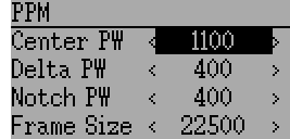
Options configurable on the PPM page:
- Center PW: Defines the time (in µsec) of the pulse that the transmitter transmits to represent to represent centered servo position. If this number doesn’t match the master transmitter, the servos will not be centered.
- Delta PW: Defines the width of the pulse (measured from center) sent by the transmitter to define max servo throw. If this value is incorrect, the servos will not achieve full range (or will travel too much)
- Notch PW: Defines the delay between the channels.
- Frame Size: Defines the total time for all channels to be transferred.
Deviation does not auto-detect when a trainer cord is plugged into the transmitter. To use Deviation with a simulator (such as Phoenix), create a new model, name it appropriately, and select PPM as the protocol. Use the Re-Init button or power-cycle to enable PPM.
10.34 Protocol: USBHID
The USBHID protocol will convert he transmitter into a USB joystick. Connecting the transmitter to a PC via the USB cable will enable the transmitter to be detected as a joystick by the computer. This may be used to enable the transmitter to control any simulators that support joystick input. Some initial calibration may be necessary and is accomplished via the control panel applet of your operating system.
11 Advanced Topics
11.1 Setting up a Buddy-Box
Deviation can be used to act as either the instructor (master) or student (slave) transmitter in a buddy-box configuration. In this mode, the instructor and student connect their respective transmitters together with a trainer cord via the DSC port. The instructor’s transmitter will actually communicate with the model, but the instructor can use a switch to allow the student to control the model. When the switch is enabled, the student’s transmitter sends input (stick) information through the trainer cord to the instructor’s transmitter and these inputs replace the instructor’s inputs.
Deviation can be configured to work with virtually any transmitter that supports either master or slave mode. Matching Deviation to a different manufacturer requires knowing the PPM parameters for the paired transmitter, and properly configuring the ‘Center PW’ and ‘Delta PW’ properly as well as knowing how many channels are transmitted and what the channel ordering is. The best place to find this information is to ask on the www.deviationtx.com forums.
11.1.1 Master Mode
Master mode is configured by selecting either ‘Channel’ or ‘Stick’ from the ‘PPM In’ spin-box in section 9.1 Model setup (Std & Adv GUI). Pressing ‘ENT’ on either ‘Stick’ or ‘Channel’ will show the ‘Trainer Cfg’ pages. The 2 modes behave slightly differently:
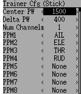
Stick: In stick mode, each input channel is mapped to a stick on the master transmitter. In this mode, the student moving the stick will behave exactly as if the instructor had moved the stick. Generally when using this mode, the student’s transmitter will directly pass the stick position (no mixing) and the instructor’s transmitter will do all necessary mixing.
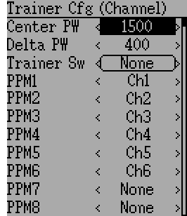
Channel: In channel mode, each input channel is mapped to an output channel on the instructor’s transmitter. In this mode, the student’s transmitter should do all necessary mixing to control the model. Care must be taken to ensure that the instructor and student transmitters are configured identically, otherwise, the model may not react well when switching between instructor and student control.
Options configurable on both Trainer Cfg pages:
- Center PW: Defines the time (in µsec) of the pulse that the student’s transmitter transmits to represent centered servo position. If this number doesn’t match the students transmitter, the servos will not be centered
- Delta PW: Defines the width of the pulse (measured from center) sent by the student’s transmitter to define max servo throw. If this value is incorrect, the servos will not achieve full range (or will travel too much)
- Trainer Sw: Defines the switch that enables the student to take control of the model
- PPM1...PPM8: Defines the mapping (either channel or input) from the student’s transmitter to the instructor’s
11.1.2 Slave Mode
Slave mode is configured by choosing ‘PPM’ as the protocol in section 9.1 Model setup (Std & Adv GUI). Pressing ‘ENT’ on the Protocol spin-box will enable setting the output options. See section 10.34 Protocol: USBHID for configuration. Note that Deviation will send the channel output data through the PPM. To use a Deviation slave transmitter with a Deviation Master configured for ‘Stick’ mode (see above), there should be no mixing done in the slave transmitter.
11.2 Setting Up FPV or Other External Inputs
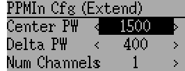
Deviation has the ability to use PPM input signals from an external source (such as an FPV setup). To configure this mode, set the PPM In mode to ‘Extend’ in section 9.1 Model setup (Std & Adv GUI).
Once enabled, press ‘ENT’ on the PPM In spin-box to configure the additional inputs.
Configuration options:
- Center PW: Defines the pulse-width for a centered input (in µsec).
- Delta PW: Defines the difference in pulse-width (from the center value) to reach min/max servo throw
- Num Channels: Defines the number of channels to input (generally no more than 8 can be supported)
11.3 Using a Trim as a Virtual Switch
Deviation has the capability to create virtual switches to supplement the mechanical switches of the transmitter. This capability is only available when using the Advanced GUI. There are 3 types of switches available:
- Momentary: The switch will be active only as long as the trim button is held
- Toggle: The switch will toggle from on-to-off or off-to-on each time the trim button is pressed
- On/Off: The Trim+ button will turn the switch on, and the ‘Trim-‘ button will turn it off-to-on
To setup a virtual switch, start by selecting the trim from the ‘Trim’ page, and entering the trim-setup page. See 9.5 Trims and Virtual Inputs (Std & Adv GUI)
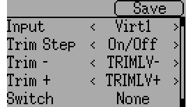
Next set the ‘Trim Step’ field to ‘Momentary’, ‘Toggle’ or ‘On/Off’. This is done by pressing the left-arrow on the ‘Trim Step’ spin-box until the value is less-than 0.1 Second select the ‘Input’ to be the virtual channel to convert to a switch (we’ll use ‘Virt1’)
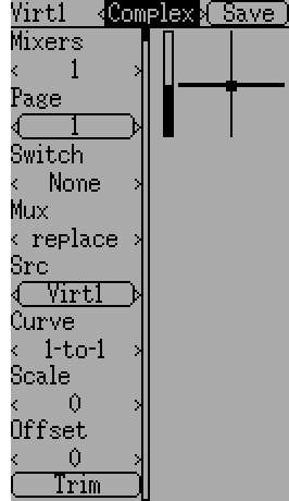
Now go to the ‘Mixer’ page, and enter the configuration for the specified Virtual Channel (Virt1 in our example)
Set the mixer-type to ‘Complex’, set the ‘src’ to the current virtual channel (‘Virt1’), set the curve to ‘1-to-1’ (Do NOT use ‘Fixed’), set the scale to ‘0’, and finally enable the ‘Trim’ button.
You can now use the virtual channel (‘Virt1’) like any other switch input. When the virtual switch is active, the virtual channel will have a value of 100, otherwise it will have a value of -100.
Note: If you use the virtual channel as a ‘Src’ (as opposed to a ‘Switch’) make sure that ‘trim’ is disabled for that mixer, otherwise the trim will be applied twice.
11.4 Swash Mixing
A swash-plate is used to control flight on an RC helicopter. The swash-plate controls the plane of rotation of the main-rotor as well as the blade pitch. A swash plate is normally connected to 3 servos known as Elevator, Aileron, and Collective, but due to its design, there is not a 1-to-1 correspondence between stick-movement and the servo movement. Instead some mixing is necessary between the throttle, elevator and aileron sticks and the swash-plate servos. This mixing is known as cyclic Collective Pitch Mixing (CCMP).
Traditionally, RC helicopters have used a flybar above or below the main rotor attached to a series of linkages to maintain stability. In these setups, the transmitter will normally do all of the mixing, and directly drive each of the 3 swash-plate servos. This configuration is known as manual-CCPM (mCCPM). Alternatively, an electronic mixer can be included on the helicopter either as part of the receiver, or between the receiver and servos, that can implement the proper mixing. This configuration is known as electronic CCPM (eCCPM) and in this case, the transmitter directly supplies aileron, elevator, and collective inputs, and the electronic mixer will convert the signals into appropriate swash-plate servo motion.
Recently, flybarless (FBL) helicopters have become more common, especially in the micro size range. These helicopters use an eCCPM system along with an electronic gyroscope to continuously adjust the swash-plate to maintain stability without the need for a physical flybar. This setup tends to be less expensive to manufacture, and also provides better stability and more precise control.
Deviation provides control for several swash-plate layouts, these include: 120°, 120° Alternate, 140°, 90°, and None. Each of these options are illustrated below:
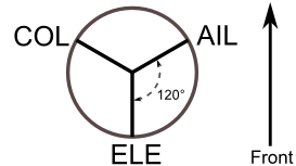
120 (3 Servo): Servos are placed around the swash-plate at 120° intervals. With Aileron input, the aileron and pitch servos tilt the swash-plate left and right; with Elevator input, the three servos tilt the swash-plate fore and aft; with Pitch input, all three servos raise the swash-plate up and down. Servos working in unison dramatically increases the torque available as well as the precision and centering.
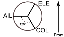
120X (3 Servo): Same as the above layout except servos are shifted 150°. With Aileron input, the three servos tilt the swash-plate left and right; with Elevator input, the elevator and pitch servos tilt the swash-plate fore and aft; with Pitch input, all three servos raise the swash-plate up and down.
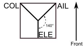
140 (3 Servo): Fundamentally, the servo operations of 140° swash-plates are almost the same as 120° swash-plates. However, the servo arrangement for elevator operation differs. 140° swash-plate CCPM offers smoother operation of the combined servos and an equal cyclic rate all around. On a 120° setup, the left/right cyclic is slightly faster than the fore/aft cyclic.
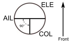
90 (3 Servo): With Aileron input, the aileron and pitch servos tilt the swash-plate left and right; with elevator input, the servos tilt the swash-plate fore and aft; with Pitch input, all three servos raise the swash-plate up and down. Most commonly used for electronic helicopters.
None: This is a special case where all mixing is done on-board the helicopter using a gyroscopic flight control system. Please refer to the specific manufacturers instructions to see how to configure mixer outputs.
Note: Some helicopters are 120 or 140, except rotated 180 degrees. In these cases you will still use the designated swash-plate type but may need to reverse specific channels.
11.5 Modifying sounds
You can edit the sounds your Devo makes, though you have to do it by mounting the transmitter as a USB drive and editing the ‘sound.ini’ file in the ‘media’ folder.
The sections, and what causes them to play, are:
- startup: Powered on.
- shutdown: Powering off.
- volume: Configuring transmitter volume.
- timer_warning: Timer is about to expire.
- alarm#: Timer # (1 to 4) has expired.
- batt_alarm: Battery low warning.
- done_binding: Binding finished.
- key_pressing: On a key press
- saving: When saving a model file.
- max_len: When you’ve exceeded the length of a string in the keyboard.
- telem_alarm#: Telemetry alarm # (1 to 6) has triggered.
In each section, you can adjust set ‘volume’ from 0 (off) to 100 (max). The rest of the entries are note names, and the value is the number of milliseconds to play that note. There is a limit of 100 notes for each sound.
The note names are ‘xx’, which is a rest (no sound played). You can then pick a note (‘a’-‘g’), possibly sharped by adding a ‘x’ if it’s ‘a’, ‘c’, ‘d’, ‘f’ or ‘g’. Finally, you can choose an octave with a single digit, ranging from ‘0’ to ‘4’. Those take you from ‘c0’ (middle C) up to ‘b4’. In addition, ‘a’, ‘ax’ and ‘b’ will play the three notes below middle C.
12 Emulator
The emulator provides a way to test Deviation on your PC without uploading the firmware to your transmitter. It provides a visual display equivalent to that of the transmitter along with a side-screen displaying the current virtual-stick/switch states as well as the Channel output that would be received by the servos.
Download and unzip the deviation-emu_devoXX-vx.y.z.zip emulator package from:
where XX is the number of your Devention transmitter. x.y.z identifies the deviation version number. Normally you should use the latest one. To start the emulator just run the exe file in the sub-directory.

The emulator controls are as follows (based an an English QWERTY keyboard):
| Keyboard | Function | Transmitter | ||
|---|---|---|---|---|
| 12e | 10 | 7e | ||
| q/a | Left-Vertical stick (Throttle in mode 2) | X | X | X |
| Q/A | Left-Vertical trim | X | X | X |
| w/s | Left-Horizontal stick (Rudder in mode 2) | X | X | X |
| W/S | Left-Horizontal trim | X | X | X |
| e/d | Right-Vertical stick (Elevator in mode 2) | X | X | X |
| E/D | Right-Vertical trim | X | X | X |
| r/f | Right-Horizontal stick (Aileron in mode 2) | X | X | X |
| R/F | Right-Horizontal trim | X | X | X |
| t/g | AUX4 | X | X | |
| T/G | Top-Left trim | X | X | |
| y/h | AUX5 | X | X | |
| Y/H | Top-Right trim | X | X | |
| u/j | AUX6 | X | ||
| i/k | AUX7 | X | ||
| z | Gear | X | X | FMODE |
| x | Rudder Dual-Rate switch | X | X | HOLD |
| c | Elevator Dual-Rate switch/SW A | X | X | |
| v | Aileron Dual-Rate switch/SW B | X | X | |
| b | Mix 0/1/2 switch | X | X | |
| n | FMode 0/1/2 switch | X | X | |
| \ | Power off | X | X | X |
| Left-arrow | Left | X | X | X |
| Right-arrow | Right | X | X | X |
| Up-arrow | Up | X | X | X |
| Down-arrow | Down | X | X | X |
| Enter | Ent | X | X | X |
| Escape | Exit | X | X | X |