
- Posts: 2
JD 395 cx-10
- kamueone
-
Topic Author
- Offline
Less
More
17 Jul 2014 14:39 #24636
by kamueone
JD 395 cx-10 was created by kamueone
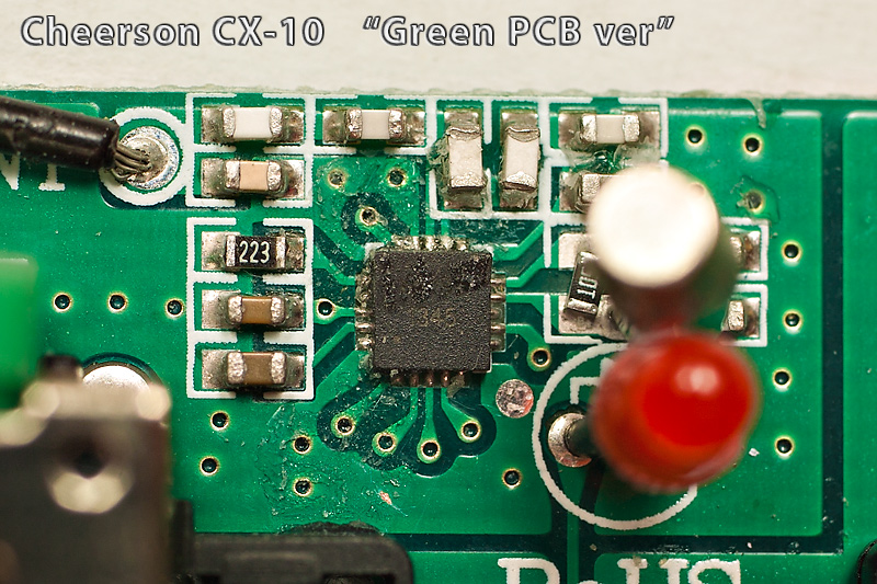
The new green Board on the Cheerson cx-10 uses the same protocol as the JD 395.
Is there a way to use that protocol with a devo 7e?
Thank you for your help,
Is there a way to use that protocol with a devo 7e?
Thank you for your help,
Please Log in or Create an account to join the conversation.
- SeByDocKy
-
- Offline
Less
More
- Posts: 1016
17 Jul 2014 15:59 #24640
by SeByDocKy
Actually, none of the Gurus here (PB, Victzh, Hexfet, etc...) have such models. I have the JXD 395, but to collect the SPI it's very hard coz the RF chip is directly soldered on the TX board. I will try to see if associated SPI pins are derivated somewhere else on the TX MCU for example.
Replied by SeByDocKy on topic JD 395 cx-10
kamueone wrote: The new green Board on the Cheerson cx-10 uses the same protocol as the JD 395.
Is there a way to use that protocol with a devo 7e?
Thank you for your help,
Actually, none of the Gurus here (PB, Victzh, Hexfet, etc...) have such models. I have the JXD 395, but to collect the SPI it's very hard coz the RF chip is directly soldered on the TX board. I will try to see if associated SPI pins are derivated somewhere else on the TX MCU for example.
Please Log in or Create an account to join the conversation.
- Daryoon
-
- Offline
Less
More
- Posts: 260
17 Jul 2014 18:52 #24645
by Daryoon
Replied by Daryoon on topic JD 395 cx-10
Maybe if you can tell us exactly where to put the logic analyzer probes...
someone with the skill to solder can grab a log.
someone with the skill to solder can grab a log.
Please Log in or Create an account to join the conversation.
- SeByDocKy
-
- Offline
Less
More
- Posts: 1016
17 Jul 2014 19:47 #24646
by SeByDocKy
It will be almost impossinle to solder on these pins (without specific material). You need 5 probes : GND, MOSI, MISO, TCK and CSN.
You can find these pins on the nRF24L01+ datasheet.
The best think to try first is to check if these pins are not linked with pins of the main MCU of the TX. On this one, soldering job will be easier
Replied by SeByDocKy on topic JD 395 cx-10
Daryoon wrote: Maybe if you can tell us exactly where to put the logic analyzer probes...
someone with the skill to solder can grab a log.
It will be almost impossinle to solder on these pins (without specific material). You need 5 probes : GND, MOSI, MISO, TCK and CSN.
You can find these pins on the nRF24L01+ datasheet.
The best think to try first is to check if these pins are not linked with pins of the main MCU of the TX. On this one, soldering job will be easier
Please Log in or Create an account to join the conversation.
- Daryoon
-
- Offline
Less
More
- Posts: 260
17 Jul 2014 20:19 #24647
by Daryoon
Replied by Daryoon on topic JD 395 cx-10
I don't think it's impossible. Looks easy to me.
Please Log in or Create an account to join the conversation.
- victzh
-
- Offline
Less
More
- Posts: 1386
17 Jul 2014 20:25 #24648
by victzh
Replied by victzh on topic JD 395 cx-10
Why do you think it's nRF24L01+ ? It looks like it, but the letters 345 are in the wrong direction.
Could you clean it with alcohol and make another photo?
In theory, the pins with fan-out (bottom side) are the ones, but the rightmost pin is not visible enough and it's unclear how to connect to it. The photo of the back would help.
Could you clean it with alcohol and make another photo?
In theory, the pins with fan-out (bottom side) are the ones, but the rightmost pin is not visible enough and it's unclear how to connect to it. The photo of the back would help.
Please Log in or Create an account to join the conversation.
- SeByDocKy
-
- Offline
Less
More
- Posts: 1016
17 Jul 2014 20:39 #24649
by SeByDocKy
Because, on the quad (on the JXD 395 at lease), there is a Beken 2423 ...
So I guess it's nRF24L01 compatible chip
Replied by SeByDocKy on topic JD 395 cx-10
victzh wrote: Why do you think it's nRF24L01+ ? It looks like it, but the letters 345 are in the wrong direction.
Could you clean it with alcohol and make another photo?
In theory, the pins with fan-out (bottom side) are the ones, but the rightmost pin is not visible enough and it's unclear how to connect to it. The photo of the back would help.
Because, on the quad (on the JXD 395 at lease), there is a Beken 2423 ...
So I guess it's nRF24L01 compatible chip
Please Log in or Create an account to join the conversation.
- Daryoon
-
- Offline
Less
More
- Posts: 260
17 Jul 2014 21:15 - 17 Jul 2014 21:23 #24651
by Daryoon
I take what I said back... taking a macro shot now.
Replied by Daryoon on topic JD 395 cx-10
victzh wrote: Why do you think it's nRF24L01+ ? It looks like it, but the letters 345 are in the wrong direction.
Could you clean it with alcohol and make another photo?
In theory, the pins with fan-out (bottom side) are the ones, but the rightmost pin is not visible enough and it's unclear how to connect to it. The photo of the back would help.
I take what I said back... taking a macro shot now.
Last edit: 17 Jul 2014 21:23 by Daryoon.
Please Log in or Create an account to join the conversation.
- SeByDocKy
-
- Offline
Less
More
- Posts: 1016
17 Jul 2014 21:22 - 17 Jul 2014 21:26 #24652
by SeByDocKy
Replied by SeByDocKy on topic JD 395 cx-10
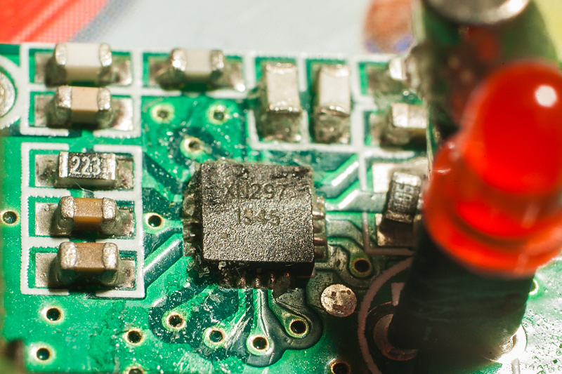
Ok Looked again for the JXD 395, it's a XN297 which is compatible nRF24L01 ....
EDIT ... Below XN297, the second number is : 345 ....
So it"s confirmed should be this chip also for the CX-10.
EDIT ... Below XN297, the second number is : 345 ....
So it"s confirmed should be this chip also for the CX-10.
Last edit: 17 Jul 2014 21:26 by SeByDocKy.
Please Log in or Create an account to join the conversation.
- Daryoon
-
- Offline
Less
More
- Posts: 260
17 Jul 2014 21:31 #24653
by Daryoon
Replied by Daryoon on topic JD 395 cx-10
Please Log in or Create an account to join the conversation.
- Daryoon
-
- Offline
Less
More
- Posts: 260
17 Jul 2014 21:35 - 17 Jul 2014 21:38 #24654
by Daryoon
Replied by Daryoon on topic JD 395 cx-10
Here's the chinese document with the pin out.
From the website:
"1 Product description
XN297 is a short distance transceiver chip, using GFSK modulation. Chip integrated RF transceiver channels, GFSK modem and digital
data link. Users only need to send / receive channels for simple setup, you can communicate. In Auto Transceive mode, the chip can root
automatically determine the data according to the response information delivery / reception was successful, so retransmission, packet loss, continue to send and wait for the other operations, with simplified
user program.
2 Recommended Operating Conditions
Power supply voltage: 3.3V
Ø Working temperature: -40 ℃ ~ 85 ℃"
Last edit: 17 Jul 2014 21:38 by Daryoon.
Please Log in or Create an account to join the conversation.
- SeByDocKy
-
- Offline
Less
More
- Posts: 1016
17 Jul 2014 21:42 #24655
by SeByDocKy
Replied by SeByDocKy on topic JD 395 cx-10
This chips must be even cheaper than the BK2423 ...
The Moontop M9911 have the same chip too ...
(see Moontop M9911 thread )
The Moontop M9911 have the same chip too ...
(see Moontop M9911 thread )
Please Log in or Create an account to join the conversation.
- SeByDocKy
-
- Offline
Less
More
- Posts: 1016
17 Jul 2014 21:46 - 17 Jul 2014 21:47 #24656
by SeByDocKy
Replied by SeByDocKy on topic JD 395 cx-10
Another document with the pinout (identical to the nRF24L01)
Last edit: 17 Jul 2014 21:47 by SeByDocKy.
Please Log in or Create an account to join the conversation.
- btoschi
-
- Offline
Less
More
- Posts: 151
17 Jul 2014 23:17 #24661
by btoschi
Replied by btoschi on topic JD 395 cx-10
Could someone post an image of the entire PCB where the MCU is visible ?
I'm usually attaching my probes to the MCU, not the RF chip itself.
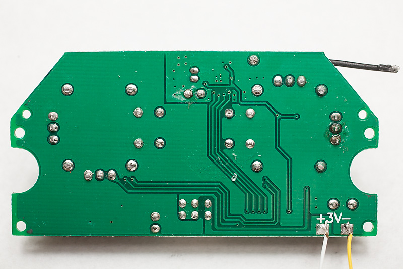
You can see traces running from RF chip to the lower part of the PCB on the backside, so these are the ones we're interested in. The contacts through the board at the lower part looks like standard pitch, easy to solder / attach SMD probes.
One can also try to solder to these "trough-board" contact rings.
I'm usually attaching my probes to the MCU, not the RF chip itself.
You can see traces running from RF chip to the lower part of the PCB on the backside, so these are the ones we're interested in. The contacts through the board at the lower part looks like standard pitch, easy to solder / attach SMD probes.
One can also try to solder to these "trough-board" contact rings.
Please Log in or Create an account to join the conversation.
- Daryoon
-
- Offline
Less
More
- Posts: 260
17 Jul 2014 23:42 - 17 Jul 2014 23:44 #24662
by Daryoon
Replied by Daryoon on topic JD 395 cx-10
Full resolution:
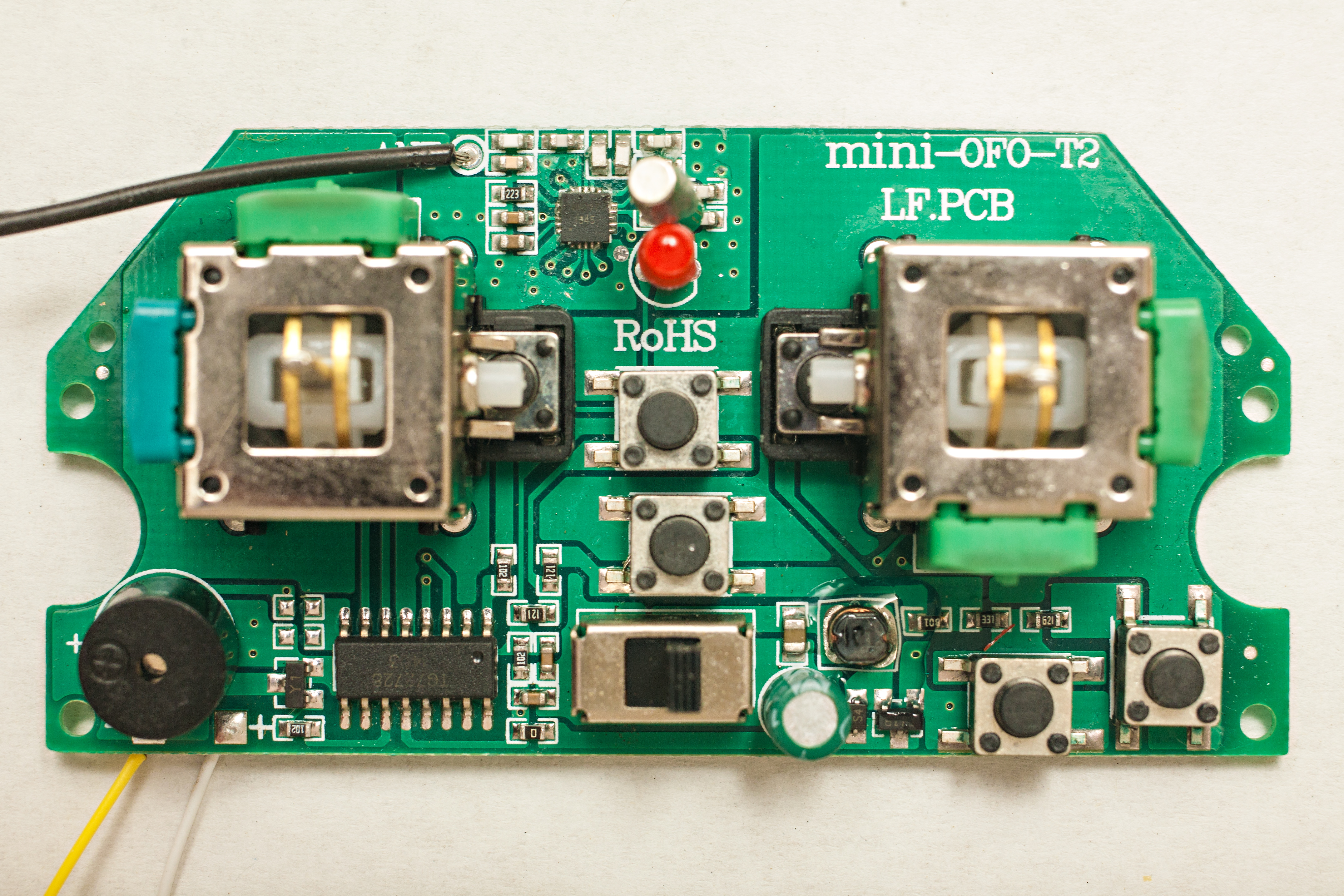
Last edit: 17 Jul 2014 23:44 by Daryoon.
Please Log in or Create an account to join the conversation.
- Daryoon
-
- Offline
Less
More
- Posts: 260
17 Jul 2014 23:55 #24664
by Daryoon
Replied by Daryoon on topic JD 395 cx-10
Here's a full resolution shot with the front and back overlayed on top of each other.
The back has been flipped horizontally so the traces lines up with the component in the front of the board.

I also have the Photoshop layered file you can change the opacity on if you have Photoshop and want a copy of the PSD.
The back has been flipped horizontally so the traces lines up with the component in the front of the board.
I also have the Photoshop layered file you can change the opacity on if you have Photoshop and want a copy of the PSD.
Please Log in or Create an account to join the conversation.
- victzh
-
- Offline
Less
More
- Posts: 1386
18 Jul 2014 15:14 #24675
by victzh
Replied by victzh on topic JD 395 cx-10
Daryoon - I must admit, that's just genius! Funny thing they didn't bother to connect MISO. Strictly speaking, you can get away without it at the cost of some reliability.
So, the answer for SPI traces - 4 wires going from the top to the bottom of the board and connected (my guess) to the bottom right 4 pins of MCU.
So, the answer for SPI traces - 4 wires going from the top to the bottom of the board and connected (my guess) to the bottom right 4 pins of MCU.
Please Log in or Create an account to join the conversation.
- Daryoon
-
- Offline
Less
More
- Posts: 260
21 Jul 2014 07:24 - 21 Jul 2014 07:25 #24719
by Daryoon
Replied by Daryoon on topic JD 395 cx-10
I hook up the Logic Analyzer on the bottom 4 legs of the MCU.
Left to Right on the MCU corresponds to:
CH1, CH2, CH3, CH4 on the Logic Analyzer
Hope you can make sense of it. LOL
hacksmods.com/files/cx10_green_capture1.zip
Left to Right on the MCU corresponds to:
CH1, CH2, CH3, CH4 on the Logic Analyzer
Hope you can make sense of it. LOL
hacksmods.com/files/cx10_green_capture1.zip
Last edit: 21 Jul 2014 07:25 by Daryoon.
Please Log in or Create an account to join the conversation.
- PhracturedBlue
-
- Offline
Less
More
- Posts: 4402
21 Jul 2014 14:33 - 21 Jul 2014 14:37 #24724
by PhracturedBlue
Replied by PhracturedBlue on topic JD 395 cx-10
Can you explain how you took the capture?
The 1st half looks like SPI, but it seems like it is a repeating pattern. I don't see anything that looks like initialization code though. The 2nd half looks decidedly not like SPI. Perhaps the wires shorted out?
I didn't check to see if I could make out any nrf commands as yet.
The 1st half looks like SPI, but it seems like it is a repeating pattern. I don't see anything that looks like initialization code though. The 2nd half looks decidedly not like SPI. Perhaps the wires shorted out?
I didn't check to see if I could make out any nrf commands as yet.
Last edit: 21 Jul 2014 14:37 by PhracturedBlue.
Please Log in or Create an account to join the conversation.
- Daryoon
-
- Offline
Less
More
- Posts: 260
21 Jul 2014 14:50 #24725
by Daryoon
Replied by Daryoon on topic JD 395 cx-10
After the LA has been hooked up.
I powered up the quad and TX.
Then moved the stick up and down to complete binding or arming of the quad.
Then I gave throttle and moved the cyclic stick around. Then moved the rudder stick around.
Then I pressed the left stick in to activate the three rate mode. I pressed the right stick in to activate flip mode. However, I didn't complete the flip.
Let me know if there's a better procedure I should be following.
Thanks.
-Daryoon
Please Log in or Create an account to join the conversation.
Time to create page: 0.156 seconds
-
Home

-
Forum
-
Development
-
Protocol Development
- JD 395 cx-10