10. Protocols
Some protocols have additional customization or limits. Each of the protocols is described below. An asterisk (‘*’) before the protocol name in the section header means a hardware module must be added to the transmitter to support the protocol. On the transmitter display the asterisk means Deviation does not detect the required module (not installed, hardware.ini not correct, or other issue communicating with the module.) More information can be found in the Module installation guide:
https://bitbucket.org/PhracturedBlue/deviation/wiki/ModuleInstallation
10.1. Protocol: DEVO
The DEVO protocol is used to maintain compatibility with the Walkera DEVO receivers/models. This protocol supports up to 12 channels. The DEVO protocol supports both auto-binding and manual-binding. If Fixed ID is set to ‘None’ the transmitter will attempt to auto-bind with the receiver every time it is powered on. If a value is set for Fixed ID, the receiver must be bound manually one-time using the ‘Bind’ button, after which it should stay bound. Note that the Fixed ID is only part of the binding procedure. Two transmitters with the Same ID cannot control the same model.
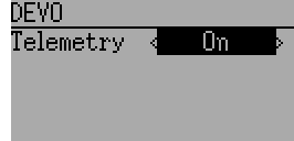
The DEVO protocol also supports enabling/disabling the telemetry capability. This option is accessed by pressing the Protocol spin-box when DEVO is shown.
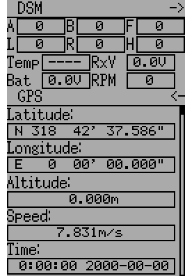
The following fields are available in Devo Telemetry. Note that not all models/receivers report all fields, and that some fields require extra modules to enable.
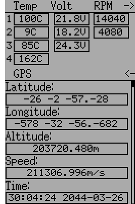
- Temp1/2/3/4: Temperature readings. These can be battery, motor, or ambient values
- Volt1/2/3: Voltage readings for receiver battery, and external batteries
- RPM1/2: Motor/Engine RPM values
- GPS Data: Current position, speed and altitude from GPS module
10.2. Protocol: WK2801
The WK2801 protocol is used to control older Walkera models. The previous Walkera models were segmented into 3 similar but not identical protocols: WK2801, WK2601, WK2401. This roughly corresponds to the number of channels supported, but many of the newer 6-channel receivers actually support the WK2801 protocol. It is recommended to try the WK2801 protocol 1st when working with older Walkera models before attempting the WK2601 or WK2401 mode, as the WK2801 is a superior protocol. The WK2801 protocol supports up to 8 channels, and both auto-binding and manual-binding. If Fixed ID is set to ‘None’ the transmitter will attempt to auto-bind with the receiver every time it is powered on. If a value is set for Fixed ID, the receiver must be bound manually one-time using the ‘Bind’ button, after which it should stay bound.
10.3. Protocol: WK2601
The WK2601 protocol is used to control older Walkera models. The previous Walkera models were segmented into 3 similar but not identical protocols: WK2801, WK2601, WK2401. This roughly corresponds to the number of channels supported, but many of the newer 6-channel receivers actually support the WK2801 protocol. It is recommended to try the WK2801 protocol 1st when working with older Walkera models before attempting the WK2601 or WK2401 mode, as the WK2801 is a superior protocol. The WK2601 protocol supports up to 7 channels, and only supports auto-binding. The fixed ID can be used, but does not prevent auto-binding during power-on.
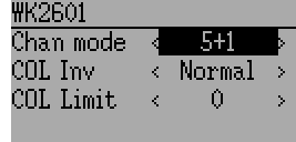
The WK2601 protocol also supports additional options. These are accessed by pressing the Protocol spin-box when Wk2601 is shown:
Chan mode: Sets how channels are processed:
- 5+1: AIL, ELE, THR, RUD, GYRO (ch 7) are proportional. Gear (ch 5) is binary. Ch 6 is disabled
- Heli: AIL, ELE, THR, RUD, GYRO are proportional. Gear (ch 5) is binary. COL (ch 6) is linked to Thr. If Ch6 >= 0, the receiver will apply a 3D curve to the Thr. If Ch6 < 0, the receiver will apply normal curves to the Thr. The value of Ch6 defines the ratio of COL to THR.
- 6+1: AIL, ELE, THR, RUD, COL (ch 6), GYRO (ch 7) are proportional. Gear (ch 5) is binary. This mode is highly experimental.
- COL Inv: Invert COL servo
- COL Limit: Set maximum range of COL servo
10.4. Protocol: WK2401
The WK2401 protocol is used to control older Walkera models. The previous Walkera models were segmented into 3 similar but not identical protocols: WK2801, WK2601, WK2401. This roughly corresponds to the number of channels supported, but many of the newer 6-channel receivers actually support the WK2801 protocol. It is recommended to try the WK2801 protocol 1st when working with older Walkera models before attempting the WK2601 or WK2401 mode, as the WK2801 is a superior protocol. The WK2401 protocol supports up to 4 channels, and only supports auto-binding. The fixed ID can be used, but does not prevent auto-binding during power-on.
10.5. Protocol: DSM2
The DSM2 protocol is used to control many Spektrum™ and JR™, as well as other models using this protocol. While the DSM2 protocol can support up to 14 channels, Deviation is currently limited to a maximum of 12. Note that many receivers with less than 8 channels require the Transmitter to send 7 or fewer channels. Make sure the # of channels is set appropriately for the receiver. DSM2 does not support auto-binding. If Fixed ID is set to None, a transmitter-specific ID is used instead. It is necessary to manually bind each model before the first use.
Note that binding does not exit until you move the AIL or ELE controls. This is so you can press the Failsafe button on some DSM receivers to set the failsafe value.
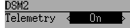
The DSM2 protocol also supports enabling/disabling the telemetry capability. This option is accessed by pressing the Protocol spin-box when DSM2 is shown.
The following fields are available in DSM2 Telemetry. Note that a dedicated telemetry module and additional sensors are needed to capture this data
- FadesA/B/L/R: The number of times each antenna has received a weak signal. Ideally these numbers should all be similar, indicating even reception to each antenna
- Loss: The number of times complete signal loss (dropped frame) occurred
- Holds: The number of times the receiver entered fail-safe mode due to loss of signal
- Volt1/2: Battery voltage for receiver and an external source
- RPM: Engine/Motor speed
- Temp: Temperature from external temperature sensor
- GPS Data: Current position, speed and altitude from GPS module
10.6. Protocol: DSMX
The DSMX protocol is used to control many Spektrum™ and JR™, as well as other models using this protocol. While the DSMX protocol can support up to 14 channels, Deviation is currently limited to a maximum of 12. Note that many receivers with less than 8 channels require the Transmitter to send 7 or less channels. Make sure the # of channels is set appropriately for the receiver. DSMX does not support auto-binding. If Fixed ID is set to None, a transmitter-specific ID is used instead. It is necessary to manually bind each model before the first use.
Note that binding does not exit until you move the AIL or ELE controls. This is so you can press the Failsafe button on some DSM receivers to set the failsafe value.
Note that unlike Spektrum™ or JR™ transmitters, Deviation will not automatically select between DSM2 and DSMX. The user must select which protocol to use.
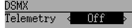
The DSMX protocol also supports enabling/disabling the telemetry capability. This option is accessed by pressing the Protocol spin-box when DSMX is shown.
The list of DSMX telemetry fields is identical to those in the DSM2 Protocol, and are documented in section 10.5 Protocol: DSM2.
10.7. Protocol: J6Pro
The J6Pro protocol is used to support Nine Eagles™ models. Only models compatible with the J6Pro transmitter can be used. Many older 4-channel Nine Eagles models used a different protocol that is unsupported. The J6Pro protocol supports up to 12 channels, although only models with 6 channels have been tested. J6Pro does not support auto-binding. If Fixed ID is set to None, a transmitter-specific ID is used instead. It is necessary to manually bind each model before the first use.
10.8. Protocol: *Flysky
The Flysky protocol is used to control Turnigy/Flysky receivers as well as a few other models using the same protocol (WL V911, Xieda 9958, etc). NOTE: This protocol requires the addition of an ‘A7105’ hardware module to function. See the following document for more information:
https://bitbucket.org/PhracturedBlue/deviation/wiki/ModuleInstallation
The Flysky protocol supports up to 12 channels, and both auto-binding and manual-binding. If Fixed ID is set to ‘None’ the transmitter will attempt to auto-bind with the receiver every time it is powered on. If a value is set for Fixed ID, the receiver must be bound manually one-time using the ‘Bind’ button, after which it should stay bound.
The Flysky protocol also supports WLToys extensions to the protocol. These are accessed by pressing the Protocol spin-box when Flysky is shown:
V9x9: Enables the extensions for the WLToys V939, V949, V959, v969, etc quadcopters.
- Lights are controlled by Channel 5
- Video is controlled by Channel 6
- Camera is controlled by Channel 7
- Flip is controlled by Channel 8
V6x6: Enables the extensions for the WLToys V636 and V686 quadcopters.
- Lights are controlled by Channel 5
- Flip is controlled by Channel 6
- Camera is controlled by Channel 7
- Video is controlled by Channel 8
- Headless mode is controlled by Channel 9
- RTH mode is controlled by Channel 10
- X and Y calibration are controlled by channels 11 and 12, respectively.
V912: Enables the extensions for the V912, V913 and V915 helicopters
Note that if these channels are assigned to a switch, turning the switch on toggles the state, and turning the switch off has no effect. Thus to turn the lights on, flip the switch assigned to Channel 5 from off to on. Flipping the switch back to off has no effect. Flipping the switch back on now turns the lights back off.
10.9. Protocol: *Hubsan4
The Hubsan4 protocol supports the Hubsan-X4 quadracopter and the Estes Proto X (but not the Proto X SLT). No other models have been tested with this protocol. NOTE: This protocol requires the addition of an ‘A7105’ hardware module to function. See the following document for more information:
https://bitbucket.org/PhracturedBlue/deviation/wiki/ModuleInstallation
The Hubsan4 protocol supports up to 7 channels, and only supports auto-binding. The fixed ID can be used, but does not prevent auto-binding during power-on. The 1 st 4 channels represent Aileron, Elevator, Throttle, and Rudder. Additional channels control the quadracopter special functions:
- Channel 5 controls the LEDs
- Channel 6 enables ‘flip’ mode
- Channel 7 Turns video on/off
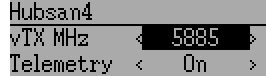
Options configurable on the Hubsan page:
- vTX MHz: Defines the frequency used by the Hubsan H107D video transmitter (Requires a 5.8GHz receiver capable of receiving and displaying video).
- Telemetry: Enable receiving of model battery voltage.
10.10. Protocol: *Joysway
The Joysway protocol supports the Joysway Caribbean model yacht, and the J4C12R receiver used in the Joysway Orion, Explorer, Dragon Force 65 model yachts and Force2 60 model catamaran. No other models or receivers have been tested with this protocol, including air versions of the J4C12R. NOTE: This protocol requires the addition of an ‘A7105’ hardware module to function. See the following document for more information:
https://bitbucket.org/PhracturedBlue/deviation/wiki/ModuleInstallation
The Joysway protocol supports up to four channels, does not support auto-binding, but will bind whenever a receiver requests binding. If Fixed ID is set to None, a transmitter-specific ID is used instead. It is necessary to bind each model before the first use.
The first channel normally controls the sheets and the second channel the rudder, but this may vary from model to model.
10.11. Protocol: *Frsky-V8
The Frsky-V8 protocol is used to control older Frsky™ receivers using the one-way protocol. NOTE: This protocol requires the addition of an ‘CC2500’ hardware module to function. See the following document for more information:
https://bitbucket.org/PhracturedBlue/deviation/wiki/ModuleInstallation
The Frsky-V8 protocol supports 8 channels, does not support auto-binding. If Fixed ID is set to None, a transmitter-specific ID is used instead. It is necessary to manually bind each model before the first use.
10.12. Protocol: *Frsky
The Frsky protocol is used to control newer (telemetry enabled) Frsky™ receivers using the two-way protocol. NOTE: This protocol requires the addition of an ‘CC2500’ hardware module to function. See the following document for more information:
https://bitbucket.org/PhracturedBlue/deviation/wiki/ModuleInstallation
The Frsky protocol supports up to 8 channels, does not support auto-binding. If Fixed ID is set to None, a transmitter-specific ID is used instead. It is necessary to manually bind each model before the first use.
The Frsky2way protocol also supports enabling/disabling the telemetry capability. This option is accessed by pressing the Protocol spin-box when Frsky2way is shown.
10.13. Protocol: *Skyartec
The Skyartec protocol is used to control Skyartec™ receivers and models. NOTE: This protocol requires the addition of an ‘CC2500’ hardware module to function. See the following document for more information:
https://bitbucket.org/PhracturedBlue/deviation/wiki/ModuleInstallation
The Skyartec protocol supports up to 7 channels, does not support auto-binding. If Fixed ID is set to None, a transmitter-specific ID is used instead. It is necessary to manually bind each model before the first use.
10.14. Protocol: *Futaba S-FHSS
The Futaba S-FHSS protocol is used to control Futaba™ receivers and models. It also used by some models of XK Innovations and has third party compatible receivers available. NOTE: This protocol requires the addition of an ‘CC2500’ hardware module to function. See the following document for more information:
https://bitbucket.org/PhracturedBlue/deviation/wiki/ModuleInstallation
The S-FHSS protocol supports up to 8 channels, and only supports auto-binding. If Fixed ID is set to None, a transmitter-specific ID is used instead. It is necessary to manually bind each model before the first use.
Traditional Futaba channel layout is following: Aileron, Elevator, Throttle, Rudder, Gear, Pitch, Aux1, and Aux2. So it is suitable for control of Collective Pitch (CP) helicopters.
Protocol resolution is 1024 steps (10 bits) out of which a bit smaller range is actually used (data by reverse engineering using third party equipment). Temporal resolution is 6.8ms. No telemetry supported.
10.15. Protocol: *V202
The V202 protocol supports the WLToys V202 quadracopter. NOTE: This protocol requires the addition of an ‘NRF24L01’ hardware module to function. See the following document for more information:
https://bitbucket.org/PhracturedBlue/deviation/wiki/ModuleInstallation
The V202 protocol supports up to 11 channels, does not support auto-binding. If Fixed ID is set to None, a transmitter-specific ID is used instead. It is necessary to manually bind each model before the first use.
The 1 st 4 channels represent Aileron, Elevator, Throttle, and Rudder. Additional channels control the quadracopter special functions:
- Channel 5 controls the blink speed
- Channel 6 enables ‘flip’ mode
- Channel 7 takes still pictures
- Channel 8 turns video on/off
- Channel 9 turns headless mode on/off
- Channel 10 causes the x axis to calibrate
- Channel 11 causes the y axis to calibrate
10.16. Protocol: *SLT
The SLT protocol is used to control TacticSLT/Anylink receivers. NOTE: This protocol requires the addition of an ‘NRF24L01’ hardware module to function. See the following document for more information:
https://bitbucket.org/PhracturedBlue/deviation/wiki/ModuleInstallation
The SLT protocol supports up to 6 channels, and only supports auto-binding. The fixed ID can be used, but does not prevent auto-binding during power-on.
10.17. Protocol: *HiSky
The HiSky protocol is used to control HiSky brand models along with the WLToys v922 v955 models. NOTE: This protocol requires the addition of an ‘NRF24L01’ hardware module to function. See the following document for more information:
https://bitbucket.org/PhracturedBlue/deviation/wiki/ModuleInstallation
The HiSky protocol supports up to 7 channels, does not support auto-binding. If Fixed ID is set to None, a transmitter-specific ID is used instead. It is necessary to manually bind each model before the first use.
10.18. Protocol: *YD717
The YD717 protocol supports the YD717 and Skybotz UFO Mini quadcopters, plus several models from Sky Walker, XinXun, Ni Hui”), and Syma through protocol options. See the Supported Modules spreadsheet for a complete list. NOTE: This protocol requires the addition of an ‘NRF24L01’ hardware module to function. See the following document for more information:
https://bitbucket.org/PhracturedBlue/deviation/wiki/ModuleInstallation
The YD717 protocol supports 9 channels and only supports auto-binding. The protocol stays in bind mode until successful.
The first four channels represent Aileron, Elevator, Throttle, and Rudder.
The fifth channel enables the auto-flip function when greater than zero. Additionally to enable auto-flips left and right the aileron channel scale must be 87 or greater. Likewise for the elevator channel and front/back flips. When auto-flip is enabled, moving the cyclic all the way in any direction initiates a flip in that direction. The YD717 requires at least four seconds between each auto-flip.
The sixth channel turns on lights when greater than zero.
The seventh channel takes a picture on transition from negative to positive.
The eighth channel starts/stops video recording on each positive transition.
The ninth channel is assigned to last feature flag available in the protocol. This may control headless mode on models that have the feature.
10.19. Protocol: *SymaX
This protocol is used on Syma models: X5C-1, X11, X11C, X12, new X4, and new X6. A variant supporting the original X5C and the X2 is included as a protocol option. (The Syma X3, old X4, and old X6 are supported with the SymaX4 option in the YD717 protocol. ) See the Supported Modules spreadsheet for a complete list. NOTE: This protocol requires the addition of an ‘NRF24L01+’ hardware module to function. Note the “plus” version of the nRF device is required to support the 250kbits/s data rate. See the following document for more information:
https://bitbucket.org/PhracturedBlue/deviation/wiki/ModuleInstallation
The SymaX protocol supports 7 channels and only supports auto-binding.
The first four channels represent Aileron, Elevator, Throttle, and Rudder.
The fifth channel is unused.
The sixth channel enables the auto-flip function when greater than zero.
The seventh channel takes a picture when the channel moves from negative to positive.
The eighth channel starts/stops video recording on each positive transition.
10.20. Protocol: *Hontai
This protocol is used on Hontai models F801 and F803.
NOTE: This protocol requires the addition of an ‘NRF24L01+’ hardware module to function. Note the “plus” version of the nRF device is required to support the 250kbits/s data rate. See the following document for more information: https://bitbucket.org/PhracturedBlue/deviation/wiki/ModuleInstallation
The first four channels represent Aileron, Elevator, Throttle, and Rudder. Additional channels control special functions:
- Channel 5 is unused
- Channel 6 enables the flip function
- Channel 7 takes a picture on positive transition through zero
- Channel 8 turns video on/off on positive transition
- Channel 9 turns headless mode on/off
- Channel 10 engages the return-to-home feature
- Channel 11 initiates calibration
10.21. Protocol: *Bayang
This protocol is used on BayangToys X6, X7, X8, X9, JJRC/Eachine H8, H10, and JJRC JJ850.
NOTE: This protocol requires the addition of an ‘NRF24L01+’ hardware module to function. Note the “plus” version of the nRF device is required to support the 250kbits/s data rate. See the following document for more information: https://bitbucket.org/PhracturedBlue/deviation/wiki/ModuleInstallation
The first four channels represent Aileron, Elevator, Throttle, and Rudder. Additional channels control special functions:
- Channel 5 is unused
- Channel 6 enables the flip function
- Channel 7 captures single photo on positive transition
- Channel 8 starts/stops video recording on positive transition
- Channel 9 turns headless mode on/off
- Channel 10 engages the return-to-home feature
10.22. Protocol: *FY326
This protocol is used on FY326 red board.
NOTE: This protocol requires the addition of an ‘NRF24L01+’ hardware module to function. Note the “plus” version of the nRF device is required to support the 250kbits/s data rate. See the following document for more information: https://bitbucket.org/PhracturedBlue/deviation/wiki/ModuleInstallation
The first four channels represent Aileron, Elevator, Throttle, and Rudder. Additional channels control special functions:
- Channel 5 is unused
- Channel 6 enables the flip function
- Channel 7 is unused
- Channel 8 is unused
- Channel 9 turns headless mode on/off
- Channel 10 engages the return-to-home feature
- Channel 11 initiates calibration
10.23. Protocol: *CFlie
The CFlie protocol is used on the CrazyFlie nano quad. It has not been tested with any other models. NOTE: This protocol requires the addition of an ‘NRF24L01+’ hardware module to function. Note the “plus” version of the nRF device is required to support the 250kbits/s data rate. See the following document for more information:
https://bitbucket.org/PhracturedBlue/deviation/wiki/ModuleInstallation
The CFlie protocol supports up to 4 channels, does not support auto-binding. If Fixed ID is set to None, a transmitter-specific ID is used instead. It is necessary to manually bind each model before the first use.
10.24. Protocol: *H377
The H377 protocol supports the NiHui H377 6 channel helicopter. It has not been tested with any other models. NOTE: This protocol requires the addition of an ‘NRF24L01’ hardware module to function. See the following document for more information:
https://bitbucket.org/PhracturedBlue/deviation/wiki/ModuleInstallation
The H377 protocol supports up to 7 channels, does not support auto-binding. If Fixed ID is set to None, a transmitter-specific ID is used instead. It is necessary to manually bind each model before the first use.
10.25. Protocol: *HM830
The HM830 protocol supports the HM830 Folding A4 Paper airplane. It has not been tested with any other models. NOTE: This protocol requires the addition of an ‘NRF24L01’ hardware module to function. See the following document for more information:
https://bitbucket.org/PhracturedBlue/deviation/wiki/ModuleInstallation
The HM830 protocol supports 5 channels and only supports auto-binding. The protocol stays in bind mode until successful.
10.26. Protocol: *KN
The KN protocol is used on the WLToys V930, V931, V966, V977 and V988 (WLToys format) as well as the Feilun FX067C, FX070C and FX071C (Feilun format) helicopters. It has not been tested with other models. NOTE: This protocol requires the addition of an ‘NRF24L01+’ hardware module to function. Note the “plus” version of the nRF device is required to support the 250kbits/s data rate. See the following document for more information:
https://bitbucket.org/PhracturedBlue/deviation/wiki/ModuleInstallation
The KN protocol supports up to 11 channels and does not support auto-binding. If Fixed ID is set to None, a transmitter-specific ID is used instead. It is necessary to manually bind each model before the first use.
Channels 1-4 are throttle, aileron, elevator and rudder. Channel 5 activates the model’s built-in dual rate. Channel 6 activates throttle hold. Channel 7 activates idle up (WL Toys V931, V966 and V977 only). Channel 8 toggles between 6G (default) and 3G stabilization. Channel 9-11 are trim channels for throttle/pitch, elevator and rudder.
10.27. Protocol: *ESky150
The ESky150 protocol supports the ESky 150 helicopter. It has not been tested with any other models. NOTE: This protocol requires the addition of an ‘NRF24L01’ hardware module to function. See the following document for more information:
https://bitbucket.org/PhracturedBlue/deviation/wiki/ModuleInstallation
The ESky150 protocol supports 4 channels and only supports auto-binding. The protocol stays in bind mode until successful.
10.28. Protocol: *Esky
Needs to be completed. NOTE: This protocol requires the addition of an ‘NRF24L01’ hardware module to function. See the following document for more information:
https://bitbucket.org/PhracturedBlue/deviation/wiki/ModuleInstallation
The Esky protocol supports up to 6 channels, does not support auto-binding. If Fixed ID is set to None, a transmitter-specific ID is used instead. It is necessary to manually bind each model before the first use.
10.29. Protocol: *BlueFly
The BlueFly protocol is used with the Blue-Fly HP100. It has not been tested with any other models. NOTE: This protocol requires the addition of an ‘NRF24L01+’ hardware module to function. Note the “plus” version of the nRF device is required to support the 250kbits/s data rate. See the following document for more information:
https://bitbucket.org/PhracturedBlue/deviation/wiki/ModuleInstallation
The BlueFly protocol supports up to 6 channels, does not support auto-binding. If Fixed ID is set to None, a transmitter-specific ID is used instead. It is necessary to manually bind each model before the first use.
10.30. Protocol: *CX10
The CX10 format supports the Cheerson CX10 quadcopter. NOTE: This protocol requires the addition of an ‘NRF24L01’ hardware module to function. See the following document for more information:
https://bitbucket.org/PhracturedBlue/deviation/wiki/ModuleInstallation
The CX10 protocol supports 9 channels and only supports auto-binding. The protocol stays in bind mode until successful. The first four channels are Aileron, Elevator, Throttle and Rudder.
Channel 5 is Rate except on the CX-10A, where it is headless mode.
Channel 6 is flip mode.
The DM007 format also uses channel 7 for the still camera, channel 8 for the video camera and channel 9 for headless mode.
The protocol has a Format option for the Blue-A, Green, DM007, Q282, JC3015-1, JC3015-2, MK33041 and Q242 quadcopters.
10.31. Protocol: *CG023
The CG023 protocol supports the Eachine CG023 and 3D X4 quadcopters. It has not been tested on other models. NOTE: This protocol requires the addition of an ‘NRF24L01’ hardware module to function. See the following document for more information:
https://bitbucket.org/PhracturedBlue/deviation/wiki/ModuleInstallation
The CG023 protocol supports 9 channels and only supports auto-binding.
The first four channels are Aileron, Elevator, Throttle and Rudder.
Channel 5 controls the LEDs.
Channel 6 controls Flip mode.
Channel 7 controls the still camera
Channel 8 controls the video camera.
Channel 9 controls headless mode.
The protocol has a Format option for the YD829 quadcopter.
10.32. Protocol: *H8_3D
The H8_3D protocol supports the Eachine H8 3D, JJRC H20 and H11D quadcopters. It has not been tested on other models. NOTE: This protocol requires the addition of an ‘NRF24L01’ hardware module to function. See the following document for more information:
https://bitbucket.org/PhracturedBlue/deviation/wiki/ModuleInstallation
The H8_3D protocol supports 11 channels and only supports auto-binding.
The first four channels are Aileron, Elevator, Throttle and Rudder.
Channel 5 controls the LEDs.
Channel 6 controls Flip mode.
Channel 7 controls the still camera
Channel 8 controls the video camera.
Channel 9 controls headless mode.
Channel 10 controls RTH mode.
Channel 11 controls camera gimball on H11D and has 3 positions.
Both sticks bottom left starts accelerometer calibration on H8 3D, or headless calibration on H20.
Both sticks bottom right starts accelerometer calibration on H20 and H11D.
10.33. Protocol: *PPM
The PPM protocol is used to output PPM on the trainer port. It will disable all radio transmission. PPM is useful for connecting to simulators, or other radio-modules that plug into the trainer port. The Fixed ID has no effect, and there is no binding associated with this protocol.
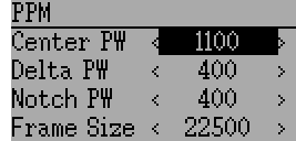
Options configurable on the PPM page:
- Center PW: Defines the time (in µsec) of the pulse that the transmitter transmits to represent to represent centered servo position. If this number doesn’t match the master transmitter, the servos will not be centered.
- Delta PW: Defines the width of the pulse (measured from center) sent by the transmitter to define max servo throw. If this value is incorrect, the servos will not achieve full range (or will travel too much)
- Notch PW: Defines the delay between the channels.
- Frame Size: Defines the total time for all channels to be transferred.
Deviation does not auto-detect when a trainer cord is plugged into the transmitter. To use Deviation with a simulator (such as Phoenix), create a new model, name it appropriately, and select PPM as the protocol. Use the Re-Init button or power-cycle to enable PPM.
10.34. Protocol: USBHID
The USBHID protocol will convert he transmitter into a USB joystick. Connecting the transmitter to a PC via the USB cable will enable the transmitter to be detected as a joystick by the computer. This may be used to enable the transmitter to control any simulators that support joystick input. Some initial calibration may be necessary and is accomplished via the control panel applet of your operating system.