Advanced Search

Search Results (Searched for: cx-10)

  • camousse
  • camousse's Avatar
24 Nov 2014 19:21
Replied by camousse on topic JD 395 cx-10

JD 395 cx-10

Category: Protocol Development

Always interesting to see another protocol with XN297, to understand this chip.
But i will not put another module (and only for CX10) in my Devo 10...
  • btoschi
  • btoschi's Avatar
24 Nov 2014 01:03 - 24 Nov 2014 01:03
Replied by btoschi on topic JD 395 cx-10

JD 395 cx-10

Category: Protocol Development

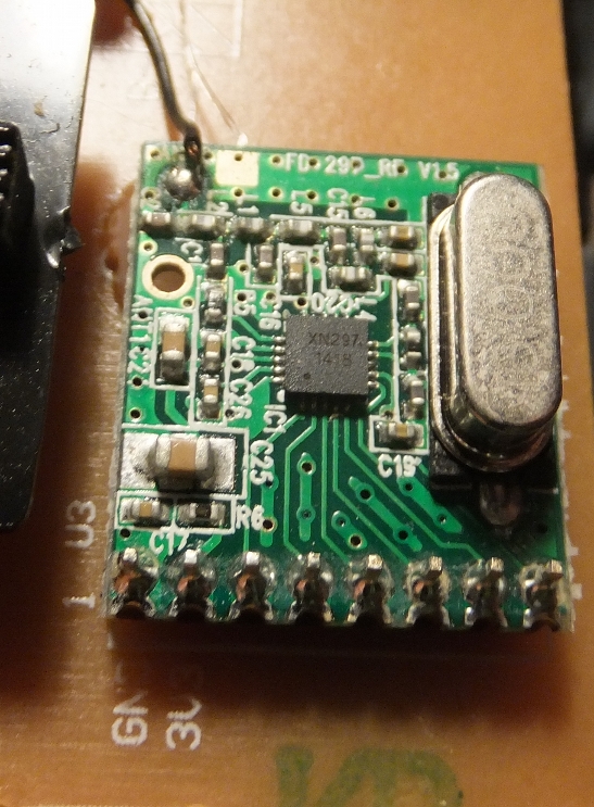
The cx10 TX has the XN297 soldered onto its main board, the picture above is from my Carrera Quadcopter's Transmitter which I've got yesterday.

It's the first extra module with XN297 I've seen for now, and, yes that's exactly the idea why I've posted this. I've sniffed SPI traffic, protocol is easy (though receiving ONE pairing packet) and should be straightforward to implement on arduino. Then we'll see if NRF can handle this, or not, and if it fails, I'll check if this module can do the job.
Then I'll check with CX-10.
  • magic_marty
  • magic_marty's Avatar
24 Nov 2014 00:23
Replied by magic_marty on topic JD 395 cx-10

JD 395 cx-10

Category: Protocol Development

Has anybody tried to remove the module from the cx10 tx and use it? Sure its possible but probably a bit difficult cause its pretty small...
  • btoschi
  • btoschi's Avatar
23 Nov 2014 23:39 - 24 Nov 2014 00:04
Replied by btoschi on topic JD 395 cx-10

JD 395 cx-10

Category: Protocol Development

I have got a (broken) toy quad from eBay which also uses XN297.
Its a Carrera R/C Micro Quadrocopter (#502002) www.carrera-rc.com/en/products/quadrocop...copter-555/#/gallery - I'll capture SPI for this soon and try to get bind working with NRF on Arduino.
Note that this TX uses a small RF module which should be relatively easy to desolder (2 or 2.54mm header) and use as XN297 board to attach to Arduino/Devo.


Pinout: GND, 3.3V, CE, CSN, SCK, MOSI, MISO, IRQ
  • camousse
  • camousse's Avatar
20 Nov 2014 09:34
Replied by camousse on topic JD 395 cx-10

JD 395 cx-10

Category: Protocol Development

I read for you problem with UDI... but it is not the same problem i think.
BK is compatible with NRF24L01, i don't think XN297 is compatible (or it is compatible if you do not change the frequency (for exemple add 500khz to all frequency), and we don't know what those 3 registers does.

For your trouble with UDI, you don't receive ACK packet (and eventually the payload associated with it because feature 0x73 seems active).
I had the same problem with ACK packet (for a CX 10 red board), but the ack packet was not really needed for protocol, so it works anyway. This board was not mine, so i can't test the solution there www.deviationtx.com/forum/protocol-devel...does-not-ack-packets
  • FDR
  • FDR's Avatar
20 Nov 2014 07:46
  • magic_marty
  • magic_marty's Avatar
20 Nov 2014 06:27
Cheerson cx-10 was created by magic_marty

Cheerson cx-10

Category: Feedback & Questions

Anybody know what the protocal is for the cheerson cx-10...
i just bought one used with the tx but wondering if i could fly it with Deviation? perhaps by adding a module to my Devo tx?

Thanks all...
<Marty>
  • btoschi
  • btoschi's Avatar
19 Nov 2014 21:24
Replied by btoschi on topic JD 395 cx-10

JD 395 cx-10

Category: Protocol Development

camousse wrote: Seems no one interested in CX 10...


I won't say so. I'm just very busy (three kids plus job keeping my spare time very low).

I'll try if I can receive bind packets of my CX-10 TX using arduino ...
I already have a similar problem with UDI Protocol (Beken 2411 not talking with NRF) I have not solved yet.
  • camousse
  • camousse's Avatar
19 Nov 2014 20:16 - 19 Nov 2014 20:16
Replied by camousse on topic JD 395 cx-10

JD 395 cx-10

Category: Protocol Development

Seems no one interested in CX 10...

I still try to receive from my CX 10 transmitter, but nothing...

Do you aware of that :
travisgoodspeed.blogspot.fr/2011/02/prom...-nrf24l01s-duty.html
But i receive only noise... I seek for the TX ADDR, in LSByte / MSByte / LSBit / MSBit but nothing...
The only way see some life from the TX with a NRF24L01 is with that (adapted for NRF24L01 channels, not WIFI):
forum.arduino.cc/index.php?topic=54795.0
With that, when i turn on TX, see something between channel 125 and channel 10... (but it is a kind of signal level)
  • camousse
  • camousse's Avatar
16 Nov 2014 20:47
Replied by camousse on topic JD 395 cx-10

JD 395 cx-10

Category: Protocol Development

Ok seems it is not my fault for the attachment.
Sorry to flood your thread but...

I found some differences between the two datasheets (nrf24l01 and xn297) :
CONFIG REGISTER : Bit 1 doesn't exist on XN297 (used to specify 2bytes CRC on NRF). CRC is always 2bytes on XN297
SETUP_AW : may be a mistake, but it seems 5bytes length address doesn't exist, 10 and 11 means 4bytes for XN297. But if it is true, this can change a lot of thing (in fact no, i try to receive with 4bytes length, LSB/MSB is not a problem as the adress is all 0xCC)
RF_CH : X297 datasheet : CHANNEL = RF_CH + 2400.

I try to receive a packet from my tx, scanning all channel, with differents paremeters, disabling CRC to get anything, and i didn't receive anything from the TX (i receive some packets, but i receive them even if the tx is turned off, but that means my receiver code works).
So :
- can be a problem with the RXADDR
- incompatible chipset (frequency, packet format, CRC..)
  • camousse
  • camousse's Avatar
16 Nov 2014 16:34
Replied by camousse on topic JD 395 cx-10

JD 395 cx-10

Category: Protocol Development

forgot the attachment (never happens to me before ;-)
  • camousse
  • camousse's Avatar
16 Nov 2014 16:24
Replied by camousse on topic JD 395 cx-10

JD 395 cx-10

Category: Protocol Development

Hi,

First, the green board and the blue board seems identical, but connection differs. The image is a green card with the blue board connections.
The strange initialization (with the write of the three registers which are undocumented in nrf24l01 datasheet) is the same for the two boards
Same bind channel, same RX ADDR / TX ADDR
But some things differs : packet length are 19bytes for blue, and only 15 bytes for green. The RX ID is missing in the green board.
The blue board enter in RX state to receive the RX id, green board never do that.
I think you have the same problem as me, and it is :
- those register change the modulation of frequencies, and channel 2 of XN297 is not the same as channel 2 of NRF24L01
- or those two chipset are not compatible (XN297 do not recognize NRF packet as valid)
++
  • camousse
  • camousse's Avatar
15 Nov 2014 22:12
Replied by camousse on topic JD 395 cx-10

JD 395 cx-10

Category: Protocol Development

Hi,
This is a bit off topic, but...

I have a CX10 with a blue board, and try to make an arduino transmitter. This transmitter seems to use the same XN297 chip.
I analyze the protocol (with a salae on the TX) and try to understand the protocol.
Basically, every 6ms, the transmitter send a packet to the receiver on differents channels (0x08, 0x1E, 0x33, 0x40, and 0x8 again...)
TX_ADDR and RX_ADDR are 5bytes, all equals to 0xCC (including bind packet).
There is no ack, bitrate is 1Mbps, but there is an activate 0X73
Data packet have this format (19bytes) :
First byte (in fact last, as it is LSByte) is packet type (55 datapacket, AA bind packet)
Next four bytes, TX id (as TX_ADDR is not used)
Next four bytes, RX id
Next two bytes a channel. LSB first. range from 1000 to 2000 (decimal)
Same for next 2 bytes
Throttle channel.
Another channel.
The last two bytes are 0x00

The binding phase is like that :
The TX send a packet with all the rxid bytes equals to 0xFF on channel 0x02 (the type of the packet is AA, and all the channels are at 1500 except for throttle, with is at 1000)
The TX wait 3ms, and start listening (ouch, devo don't have CE pin without multimodule)
The TX receive a packet from the receiver, equals to the previous packet except for RXid
The TX send a packet with the rxid (same as previous)
The TX receive a packet with some different value in channels.
The TX start to send packet like above, until the user move the throttle stick up and down
The TX send data packet(packet type = 55)

In fact, i'm not sure for the last transition between bind and data packet, as i'm stuck receiving the first packet from the receiver...
I don't receive anything.
The strange thing is, in the initialization process (at the very beginning) :
register 1F is writed with 4C/84/67/9C/20/
register 1E is writed with C9/9A/B0/61/BB/AB/9C/
register 19 is writed with 0B/DF/C4/A7/03/
More funny :
Just after that, comes the TX_ADDR and RX_ADDR (5bytes, all equals to 0xCC)
Common initialization things (EN_AA, Flush, SETUP, RF_CH, RETR, PW_P0, DYNPD...
The RX_ADDR is set to 5 bytes
And... the TX_ADDR is set again, but with only one byte (CC)
I try to put my NRF24L01 attached to my arduino as receiver only, and start binding with the original radio.. and i don't receive anything.
I even try to copy the initialization process exactly (writing the 1F register) without success
I'm pretty sure i don't receive anything, but i don't know if my first packet is received correctly by the receiver.


Any ideas ?

Thanks.
  • Ziggy
  • Ziggy's Avatar
14 Oct 2014 15:50
Replied by Ziggy on topic JD 395 cx-10

JD 395 cx-10

Category: Protocol Development

If there is something to test or any way to to help,i would love to, also have a green one and and Devo 7e with nrf24l01
  • SeByDocKy
  • SeByDocKy's Avatar
08 Oct 2014 08:02
Replied by SeByDocKy on topic JD 395 cx-10

JD 395 cx-10

Category: Protocol Development

btoschi wrote: I've sniffed some traffic on my green CX-10 (gosh, I always thought it was a red one :D )

Some observations:
Pin 13 of MCU seems to be connected to CE (Pin1 of XN297, next to CSN), not to MOSI. After init its low during SPI transfer, then high until next transfer (RF chip goes to idle after transmission, saves battery).

SPI traffic matches, but I think I've found the real TX ID:
Mine has bytes 1-4 in data packet set to 87 10 89 67 (was 0B 06 34 12 in the other capture) and uses RF channels 41, 0A, 1E, 2D for hopping (16, 33, 40, 0E in other capture).
All transmissions use CC CC CC CC as RX/TX address, but the TX ID above seems to select between (some) RF chanel hopping sequences, plus I'm pretty sure RX dicards any packets with different ID after binding with one transmitter.

Some features here look very familiar compared with UDI protocols, besides this one completely lacks RX to TX communication (which makes UDI the "never reaching the last bind step"-beast I'm still struggling with).

I'll test hexfet's code on my Devo now, let's hope that's an easy walk to do having a CX-10 plus debugging and coding skills :D

Edit:
Adjusted code to match timings from my capture

#define BIND_COUNT 4238
#define PACKET_PERIOD   1510
NRF24L01_SetBitrate(NRF24L01_BR_250K);           // 250kpbs
Note that the SPI captures shows W_REGISTER(RF_SETUP) 07, thus its 250kbps data rate, while the diff I have here (20140809) used 1Mbps.
Tried with my TX ID and channel sequence, but still it does not bind (front LEDs would blink slower), double checked that my V2x2 is binding properly.


Great work Bjorn,

You are close to hack this one too ....
Hum it will be great to add the NRF24L01_SetBitrate(NRF24L01_BR_250K); feature too for the V2x2 protocol ... coz I am planning to install bradwii (thanks victzh again) on one my V2x2 compatible quad :) (in order to extend range). Now I understand why, the control range is good with this XN297 coz they reduce datarate in order to improve RX sensibility
  • btoschi
  • btoschi's Avatar
07 Oct 2014 20:30 - 07 Oct 2014 21:44
Replied by btoschi on topic JD 395 cx-10

JD 395 cx-10

Category: Protocol Development

I've sniffed some traffic on my green CX-10 (gosh, I always thought it was a red one :D )

Some observations:
Pin 13 of MCU seems to be connected to CE (Pin1 of XN297, next to CSN), not to MOSI. After init its low during SPI transfer, then high until next transfer (RF chip goes to idle after transmission, saves battery).

SPI traffic matches, but I think I've found the real TX ID:
Mine has bytes 1-4 in data packet set to 87 10 89 67 (was 0B 06 34 12 in the other capture) and uses RF channels 41, 0A, 1E, 2D for hopping (16, 33, 40, 0E in other capture).
All transmissions use CC CC CC CC as RX/TX address, but the TX ID above seems to select between (some) RF chanel hopping sequences, plus I'm pretty sure RX dicards any packets with different ID after binding with one transmitter.

Some features here look very familiar compared with UDI protocols, besides this one completely lacks RX to TX communication (which makes UDI the "never reaching the last bind step"-beast I'm still struggling with).

I'll test hexfet's code on my Devo now, let's hope that's an easy walk to do having a CX-10 plus debugging and coding skills :D

Edit:
Adjusted code to match timings from my capture
#define BIND_COUNT 4238
#define PACKET_PERIOD   1510
NRF24L01_SetBitrate(NRF24L01_BR_250K);           // 250kpbs
Note that the SPI captures shows W_REGISTER(RF_SETUP) 07, thus its 250kbps data rate, while the diff I have here (20140809) used 1Mbps.
Tried with my TX ID and channel sequence, but still it does not bind (front LEDs would blink slower), double checked that my V2x2 is binding properly.
  • hexfet
  • hexfet's Avatar
07 Oct 2014 16:02
Replied by hexfet on topic SOLVED: CX-10 binds but does not ACK packets

SOLVED: CX-10 binds but does not ACK packets

Category: Protocol Development

Glad to hear you got it sorted. Thanks for updating.
  • alibenpeng
  • alibenpeng's Avatar
07 Oct 2014 09:27
Replied by alibenpeng on topic SOLVED: CX-10 binds but does not ACK packets

SOLVED: CX-10 binds but does not ACK packets

Category: Protocol Development

Another update:

Turns out I had two faulty nRF24 modules with exactly the same fault. Must have been the exposure to 5V I guess, but I can't be sure.

Anyway, I received the new nRF24 module and it works as intended. Bind packets get ACKed now and I can also bind the crazyflie, which didn't work before.

The erratic behaviour of the quad stayed, but I'm confident that's fue to it having crashed a few times too often. Actually, after poking around a bit, I suspect that one or more solder joints on or around the IMU were bad, as reflowing the whole area around the MPU6050 seems to have fixed the problem.

So, case closed and lesson learned: Be careful not to connect 5V to your nRF24 module. Even if it seems to work at first glance it might still be broken in a less obvious way.

Thanks everyone for the support.
  • Wene001
  • Wene001's Avatar
02 Oct 2014 19:24 - 02 Oct 2014 19:24
Replied by Wene001 on topic volantex vector 28

volantex vector 28

Category: Protocol Development

No luck
Tried to bind with CX-10
Red pcb
Should work with Skywlkr Protocol but Dienst

Waiting for the Single board Universal Module for my 6s and my 12s
  • SeByDocKy
  • SeByDocKy's Avatar
30 Sep 2014 15:48
Replied by SeByDocKy on topic JD 395 cx-10

JD 395 cx-10

Category: Protocol Development

hexfet wrote:

SeByDocKy wrote: Do you need also some informations from the RX part ?

More info is almost always a good thing. A couple SPI traces from the receiver would be interesting too - see if it's receiving anything at all from the Devo and what a successful bind looks like. But can't offer any hope it will help with binding to an nRF chip...


I can't believe they used the non nRF24L01 compatible mode ....
Hope that :) The problem with the RX .. is to capture SPI log ... so tiny chips
Displaying 621 - 640 out of 736 results.
Time to create page: 0.683 seconds
Powered by Kunena Forum