
- Posts: 244
Devo power regulators
- silpstream
-
Topic Author
- Offline
Less
More
15 Apr 2016 19:02 - 15 Apr 2016 19:08 #46577
by silpstream
Devo power regulators was created by silpstream
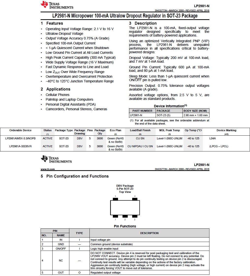
I was looking at the power regulators that I had in my transmitter (7e) prior to adding more RF modules to better understand the load that could be put on it. The part number I had on the 3.3v regulator is "LPCL" which I believe is the Texas Instruments LP2981 rated for 100mA and capable of an input voltage of up to 16v. This seemed really low for powering the entire transmitter so I started searching for other regulators as well as looking at the regulation circuitry onboard. This led to a few interesting discoveries (for me at least), so I decided to ask here in hopes of getting more information to see if there is a better way to power everything.
1. Bypass Capacitor on Pin 4
There is a bypass capacitor on pin 4 of the power regulator, but the manufacturer's data sheet explicitly states (and warns) that the pin should be left floating. This indicated to me that Walkera may have designed the circuit for a different regulator and due to cost or supply reasons decided to put the LP2981 in instead, but didn't quite fix things for pin compatibility. I also took a look at the other Devos to see how their circuits are, and from the various pictures floating around I could only find 2 part numbers "LPCL" and "L04A", both of which are the LP2981. Also in all the pictures, it shows a bypass capacitor on pin 4. Except for the one picture from our download area of the Devo10 which seems to have the capacitor omitted or removed.
Given the pin configuration and the various capacitors making up the circuit, I believe that we can drop in a LP2985 (150mA) or the MIC5219 (500mA). I'm leaning towards replacing the regulator (with the MIC5219) as opposed to removing the capacitor as I believe the extra bypass capacitor will reduce noise within the circuit.
(Question) I'd like to know if any of you have a different part number on your regulator that might indicate to us the original part that Walkera had designed for.
2. There is another 3.3v regulator built into the stock Devo7e RF module
The regulator on my RF module has a part number of "JY=T08", I couldn't find the actual data sheet for this, but the sot-23-5 foot print and surrounding circuitry looked like a regulator's circuit so I put my multimeter across it and measured 3.3v. It gets fed VBAT from pin 6 (counting from the left) of the RF module after going through a diode (Part "SL" on at the bottom right of the RF module) back to pin1 of the main boards regulator.
This leads me to think that we shouldn't be connecting our extra modules to VDD on the programming header, as it adds out-of-spec load to the existing regulator. We should instead hook up another 3.3v LDO to pin 6 and 7 on the stock RF module to power our extra modules. This might give better isolation to noise as well as allow the stock regulator to run the way it was designed. We could probably use the AMS1117 module that I saw in another thread, but have 3 regulators inside rather than remove and replace the stock one with the AMS1117.
(Question) I can't seem to identify the switch circuit part. It seems to have some sort of 3 pin transistor like component (Part number "F0KIL") as well as some NPN and PNP transistors (I'm assuming as some sort of electronic switch) to do the actual power up since Walkera has a soft on/off switch installed. I also saw in another thread that someone managed to blow up the "F0KIL" part. Thus without knowing enough about the part, I can't be certain that the switching circuitry can take the load of 3 regulators. Anyone have a view on this or extra information?
I'm guessing that since all the demo transmitters have similar power circuits, the findings we get from here can apply to all the transmitters.
Pictures of the interesting bits:

Thanks all!
1. Bypass Capacitor on Pin 4
There is a bypass capacitor on pin 4 of the power regulator, but the manufacturer's data sheet explicitly states (and warns) that the pin should be left floating. This indicated to me that Walkera may have designed the circuit for a different regulator and due to cost or supply reasons decided to put the LP2981 in instead, but didn't quite fix things for pin compatibility. I also took a look at the other Devos to see how their circuits are, and from the various pictures floating around I could only find 2 part numbers "LPCL" and "L04A", both of which are the LP2981. Also in all the pictures, it shows a bypass capacitor on pin 4. Except for the one picture from our download area of the Devo10 which seems to have the capacitor omitted or removed.
Given the pin configuration and the various capacitors making up the circuit, I believe that we can drop in a LP2985 (150mA) or the MIC5219 (500mA). I'm leaning towards replacing the regulator (with the MIC5219) as opposed to removing the capacitor as I believe the extra bypass capacitor will reduce noise within the circuit.
(Question) I'd like to know if any of you have a different part number on your regulator that might indicate to us the original part that Walkera had designed for.
2. There is another 3.3v regulator built into the stock Devo7e RF module
The regulator on my RF module has a part number of "JY=T08", I couldn't find the actual data sheet for this, but the sot-23-5 foot print and surrounding circuitry looked like a regulator's circuit so I put my multimeter across it and measured 3.3v. It gets fed VBAT from pin 6 (counting from the left) of the RF module after going through a diode (Part "SL" on at the bottom right of the RF module) back to pin1 of the main boards regulator.
This leads me to think that we shouldn't be connecting our extra modules to VDD on the programming header, as it adds out-of-spec load to the existing regulator. We should instead hook up another 3.3v LDO to pin 6 and 7 on the stock RF module to power our extra modules. This might give better isolation to noise as well as allow the stock regulator to run the way it was designed. We could probably use the AMS1117 module that I saw in another thread, but have 3 regulators inside rather than remove and replace the stock one with the AMS1117.
(Question) I can't seem to identify the switch circuit part. It seems to have some sort of 3 pin transistor like component (Part number "F0KIL") as well as some NPN and PNP transistors (I'm assuming as some sort of electronic switch) to do the actual power up since Walkera has a soft on/off switch installed. I also saw in another thread that someone managed to blow up the "F0KIL" part. Thus without knowing enough about the part, I can't be certain that the switching circuitry can take the load of 3 regulators. Anyone have a view on this or extra information?
I'm guessing that since all the demo transmitters have similar power circuits, the findings we get from here can apply to all the transmitters.
Pictures of the interesting bits:
Thanks all!
Last edit: 15 Apr 2016 19:08 by silpstream.
- Fernandez
-
- Offline
Less
More
- Posts: 983
16 Apr 2016 19:59 #46644
by Fernandez
Replied by Fernandez on topic Devo power regulators
In my devo 7e I agree that small regulator became too hot too touch........ I replaced it with an external pololu stepup/down regulator, an AMS1117 3v3 regulator also works but it has some dropout voltage, so on 4 cell nimh, it might suddenly switch off your tx.....
www.deviationtx.com/forum/6-general-disc...rvolted-devo7e#43231
Altough after replacing the voltage regulator, still it did not solve my voltage fluctuation displayed on the Tx when using Frsky protocol...........
www.deviationtx.com/forum/6-general-disc...rvolted-devo7e#43231
Altough after replacing the voltage regulator, still it did not solve my voltage fluctuation displayed on the Tx when using Frsky protocol...........
- mwm
-
- Offline
16 Apr 2016 23:46 #46669
by mwm
Do not ask me questions via PM. Ask in the forums, where I'll answer if I can.
My remotely piloted vehicle ("drone") is a yacht.
Replied by mwm on topic Devo power regulators
We now have a user-editable wiki that includes a hardware mod section. If you could move this tutorial into that, it would stay a lot easier for people to find!
And I think I'm going to be saying this a lot in the near future.
And I think I'm going to be saying this a lot in the near future.
Do not ask me questions via PM. Ask in the forums, where I'll answer if I can.
My remotely piloted vehicle ("drone") is a yacht.
- YJ
-
- Offline
Less
More
- Posts: 27
04 May 2016 04:49 #47713
by YJ
Replied by YJ on topic Devo power regulators
I ordered one, too. Thanks for the info!
On its way. Can't wait to see how it performs.
In the mean time, I'm starting to think, while this seems a good fit for NiMH batteries, if using Lipo, the LDO in the Cypress module will still be stressed by the high input voltage (raw voltage - ~1v), so a 5V step down is probably needed for the cypress module.
Yet another observation, I've left the unit operating in 24L01 and 7105 mode @100mW for an extended time (~1hour) and the on-board tiny ldo (next to the two AE caps) gets barely warm. This is running with a fully charged 2s lipo (~8.2V). Based on that, I'm wondering if it's necessary to replace the onboard ldo with a beefier one, if effeciency is not a concern. Or did I miss something?
Fernandez wrote: In my devo 7e I agree that small regulator became too hot too touch........ I replaced it with an external pololu stepup/down regulator, an AMS1117 3v3 regulator also works but it has some dropout voltage, so on 4 cell nimh, it might suddenly switch off your tx.....
www.deviationtx.com/forum/6-general-disc...rvolted-devo7e#43231
Altough after replacing the voltage regulator, still it did not solve my voltage fluctuation displayed on the Tx when using Frsky protocol...........
- YJ
-
- Offline
Less
More
- Posts: 27
04 May 2016 05:20 #47714
by YJ
Replied by YJ on topic Devo power regulators
This is indeed a good post.
I too have some doubts regarding how the Devo7e power train works and this prompted me to dig a bit further.
Interestingly, this is what I found
Regardless of which module you use (cy, 2401, 7105, 2500), when transmitting at 100mW, the current draw at the battery connector is ~150mA (Hisky protocol draws less, around 115mA) and @100uW, 110-134mA, depending on the module you choose.
What's funny is that when you choose "ppm", as in simulator mode, the whole unit still draws 110mA... Suspect the built-in cypress module draws constant current even not in use. So I removed the diode feeding the power to the Cypress module however it still draws around 110mA, only that now the tiny on-board ldo quickly gets hot. Measuring the module pin, I can see the module is now being powered by 3.3V as opposed to "directly" (well, sort of) powered by the battery voltage. I powered the module with an external source, and all of a sudden, the whole units draws a mere 13mA!
So here's what I believe,
First, since the built-in RF module is powered by battery and does not go through the 3.3V LDO, the tiny on board regulator, rated at 100mA, is adequate for what it's designed for (13mA for the main board).
The RF module is dual-powered by 3.3V and battery voltage, which ever is higher. In most cases, the power comes from the battery. I've not seen the inside of the module but heard there's also ldo inside. If so, the input voltage is important as a higher input voltage (e.g., when using 2S lipo) will cause excess heat and probably exceed the rf module's ldo's thermal limit. When testing the unit with a 2S lipo in 100mW DSM2 mode, the module quickly gets warm. Keeping the input voltage to around 5V is vital to avoid stressing the rf module regulator.
For additonal rf modules, energy conversion with 0 loss and no overhead requires only This email address is being protected from spambots. You need JavaScript enabled to view it.. In real world, let's assume the overall effeciency+ overhead is 40%, this will result in a current draw of about 70mA from the LDO. Adding the main board consumption of 13mA, it's about 83mA. Not the best margin for a 100mA ldo but we should be fine. When I get a chance, I'll take an actual measurement on the external rf module's current draw from 3.3V to be sure.
Given the above, I will definitely add a 5V step-down regulator for the Cypress module, especially since I do plan to use 2S Lipo. This will not only avoid stressing the Cyp module but also increase the run time from the Lipo. And since I already have 3.3V step down module on its way, I will replace the on board 3.3v ldo as well. Not absolutely necessary from reliability perspective but it does have the benefit of extending run time.
Cheers.
silpstream wrote: I was looking at the power regulators that I had in my transmitter (7e) prior to adding more RF modules to better understand the load that could be put on it. The part number I had on the 3.3v regulator is "LPCL" which I believe is the Texas Instruments LP2981 rated for 100mA and capable of an input voltage of up to 16v. This seemed really low for powering the entire transmitter so I started searching for other regulators as well as looking at the regulation circuitry onboard. This led to a few interesting discoveries (for me at least), so I decided to ask here in hopes of getting more information to see if there is a better way to power everything.
1. Bypass Capacitor on Pin 4
There is a bypass capacitor on pin 4 of the power regulator, but the manufacturer's data sheet explicitly states (and warns) that the pin should be left floating. This indicated to me that Walkera may have designed the circuit for a different regulator and due to cost or supply reasons decided to put the LP2981 in instead, but didn't quite fix things for pin compatibility. I also took a look at the other Devos to see how their circuits are, and from the various pictures floating around I could only find 2 part numbers "LPCL" and "L04A", both of which are the LP2981. Also in all the pictures, it shows a bypass capacitor on pin 4. Except for the one picture from our download area of the Devo10 which seems to have the capacitor omitted or removed.
Given the pin configuration and the various capacitors making up the circuit, I believe that we can drop in a LP2985 (150mA) or the MIC5219 (500mA). I'm leaning towards replacing the regulator (with the MIC5219) as opposed to removing the capacitor as I believe the extra bypass capacitor will reduce noise within the circuit.
(Question) I'd like to know if any of you have a different part number on your regulator that might indicate to us the original part that Walkera had designed for.
2. There is another 3.3v regulator built into the stock Devo7e RF module
The regulator on my RF module has a part number of "JY=T08", I couldn't find the actual data sheet for this, but the sot-23-5 foot print and surrounding circuitry looked like a regulator's circuit so I put my multimeter across it and measured 3.3v. It gets fed VBAT from pin 6 (counting from the left) of the RF module after going through a diode (Part "SL" on at the bottom right of the RF module) back to pin1 of the main boards regulator.
This leads me to think that we shouldn't be connecting our extra modules to VDD on the programming header, as it adds out-of-spec load to the existing regulator. We should instead hook up another 3.3v LDO to pin 6 and 7 on the stock RF module to power our extra modules. This might give better isolation to noise as well as allow the stock regulator to run the way it was designed. We could probably use the AMS1117 module that I saw in another thread, but have 3 regulators inside rather than remove and replace the stock one with the AMS1117.
(Question) I can't seem to identify the switch circuit part. It seems to have some sort of 3 pin transistor like component (Part number "F0KIL") as well as some NPN and PNP transistors (I'm assuming as some sort of electronic switch) to do the actual power up since Walkera has a soft on/off switch installed. I also saw in another thread that someone managed to blow up the "F0KIL" part. Thus without knowing enough about the part, I can't be certain that the switching circuitry can take the load of 3 regulators. Anyone have a view on this or extra information?
I'm guessing that since all the demo transmitters have similar power circuits, the findings we get from here can apply to all the transmitters.
Pictures of the interesting bits:
Thanks all!
- Fernandez
-
- Offline
Less
More
- Posts: 983
04 May 2016 07:52 #47716
by Fernandez
Replied by Fernandez on topic Devo power regulators
I do notnunderstand term "bypass capacitor".
To me the pin may not be connected to potential means dc. The capacitor is just to ensure the pin is free of any noise and not pick up any rf signals.
To me the pin may not be connected to potential means dc. The capacitor is just to ensure the pin is free of any noise and not pick up any rf signals.
- silpstream
-
- Offline
Less
More
- Posts: 244
04 May 2016 18:15 #47756
by silpstream
Replied by silpstream on topic Devo power regulators
You're probably right about voltage being too high if using a lipo. Would be interesting to see how we can do that while still maintaining the stock regulator and being able to keep VBAT reading for deviation. Might be possible if we can find the right items to desolder or traces to cut.YJ wrote: In the mean time, I'm starting to think, while this seems a good fit for NiMH batteries, if using Lipo, the LDO in the Cypress module will still be stressed by the high input voltage (raw voltage - ~1v), so a 5V step down is probably needed for the cypress module.
I never tried and had assumed that the stock regulator would get hot when trying to drop 8.2V to 3.3V. The current handling capability should be inversely related to the input voltage after all.YJ wrote: Yet another observation, I've left the unit operating in 24L01 and 7105 mode @100mW for an extended time (~1hour) and the on-board tiny ldo (next to the two AE caps) gets barely warm. This is running with a fully charged 2s lipo (~8.2V). Based on that, I'm wondering if it's necessary to replace the onboard ldo with a beefier one, if effeciency is not a concern. Or did I miss something?
I came to this conclusion also. There is indeed another old inside the module.YJ wrote: First, since the built-in RF module is powered by battery and does not go through the 3.3V LDO, the tiny on board regulator, rated at 100mA, is adequate for what it's designed for (13mA for the main board).
This I can't quite confirm as I haven't tried it, but I have a hard time imagining how it can dual power. Will need to trace the pcbs more to figure this out.YJ wrote: The RF module is dual-powered by 3.3V and battery voltage, which ever is higher. In most cases, the power comes from the battery. I've not seen the inside of the module but heard there's also ldo inside. If so, the input voltage is important as a higher input voltage (e.g., when using 2S lipo) will cause excess heat and probably exceed the rf module's ldo's thermal limit.
Please do, I'd be interested to know your findings.YJ wrote: When I get a chance, I'll take an actual measurement on the external rf module's current draw from 3.3V to be sure.
What are you thinking of replacing it with?YJ wrote: And since I already have 3.3V step down module on its way, I will replace the on board 3.3v ldo as well.
- silpstream
-
- Offline
Less
More
- Posts: 244
04 May 2016 18:22 #47758
by silpstream
 ) In general if the reference application from the data sheet says NC, I normally leave it literally not connected, but that's just me.
Replied by silpstream on topic Devo power regulators
It is also known as a decoupling capacitor. Try here: https://en.wikipedia.org/wiki/Decoupling_capacitorFernandez wrote: I do notnunderstand term "bypass capacitor".
I'm not sure if it is that simplistic. The data sheet doesn't show a block diagram of whats behind the "NC" pin (pin4), thus I can't really say how it will get affected. Current may not flow in the traditional sense through this capacitor, but I believe there will still be a potential across it. (I hate figuring electronics versus physics for capacitors...Fernandez wrote: To me the pin may not be connected to potential means dc. The capacitor is just to ensure the pin is free of any noise and not pick up any rf signals.
- HappyHarry
-
- Offline
Less
More
- Posts: 1136
04 May 2016 19:01 #47761
by HappyHarry
Replied by HappyHarry on topic Devo power regulators
yeah it clearly states no potential, no ground. though it also states that it's used for calibration/adjustment perhaps they were off the 3.3v and these caps correct this? but I'm pretty much a newb electronics wise so don't beat me if I'm wrong lol
- silpstream
-
- Offline
Less
More
- Posts: 244
04 May 2016 19:25 #47766
by silpstream
Replied by silpstream on topic Devo power regulators
Could you tell me which diode you removed? Or attach a picture indicating the diode? Thanks!YJ wrote: So I removed the diode feeding the power to the Cypress module however it still draws around 110mA, only that now the tiny on-board ldo quickly gets hot. Measuring the module pin, I can see the module is now being powered by 3.3V as opposed to "directly" (well, sort of) powered by the battery voltage. I powered the module with an external source, and all of a sudden, the whole units draws a mere 13mA!
- silpstream
-
- Offline
Less
More
- Posts: 244
04 May 2016 19:26 #47767
by silpstream
Replied by silpstream on topic Devo power regulators
I'm quite sure the capacitor is not there to help correct for 3.3v... lolHappyHarry wrote: yeah it clearly states no potential, no ground. though it also states that it's used for calibration/adjustment perhaps they were off the 3.3v and these caps correct this? but I'm pretty much a newb electronics wise so don't beat me if I'm wrong lol
- YJ
-
- Offline
Less
More
- Posts: 27
05 May 2016 00:45 #47788
by YJ
Replied by YJ on topic Devo power regulators
It's the "part SL diode" in your original post, at 5:25-ish of the RF module. On the right side it appears to be the battery voltage, on the left, battery voltage-0.5V. When this diode is removed, you can still measure about 3.3V on the left side hence "dual power" for lack of a better wor/description since I don't have the schematics and/or figured out the actual wiring of that area.
silpstream wrote:
Could you tell me which diode you removed? Or attach a picture indicating the diode? Thanks!YJ wrote: So I removed the diode feeding the power to the Cypress module however it still draws around 110mA, only that now the tiny on-board ldo quickly gets hot. Measuring the module pin, I can see the module is now being powered by 3.3V as opposed to "directly" (well, sort of) powered by the battery voltage. I powered the module with an external source, and all of a sudden, the whole units draws a mere 13mA!
- silpstream
-
- Offline
Less
More
- Posts: 244
05 May 2016 04:49 #47800
by silpstream
Replied by silpstream on topic Devo power regulators
Ok. That's interesting to know. I was actually hoping that it would be isolated so that we could add in another pre-regulator for the rf module while still retaining the ability to read battery voltage in the software. I'll see if I can trace some of the tracks.
- YJ
-
- Offline
Less
More
- Posts: 27
05 May 2016 20:20 #47834
by YJ
Replied by YJ on topic Devo power regulators
I measured the current through that tiny "LPCL" ldo. It remains at 1.6mA, regardless the module being selected (or not selected, as in ppm mode). For this experiment, the external module is tied to "VDD" on the programming header which is at 6:00 of the on-board rf module.
Apparently there's another regulator supplying that "VDD" node and at least the back light of the LCD. Perhaps on the otherside of the PCB under the display module? I'm hoping someone has already done similar poking and figured this out so that we don't re-invent the wheel here.
Apparently there's another regulator supplying that "VDD" node and at least the back light of the LCD. Perhaps on the otherside of the PCB under the display module? I'm hoping someone has already done similar poking and figured this out so that we don't re-invent the wheel here.
- HappyHarry
-
- Offline
Less
More
- Posts: 1136
05 May 2016 22:20 #47840
by HappyHarry
hey i said don't beat me lol
Replied by HappyHarry on topic Devo power regulators
silpstream wrote:
I'm quite sure the capacitor is not there to help correct for 3.3v... lolHappyHarry wrote: yeah it clearly states no potential, no ground. though it also states that it's used for calibration/adjustment perhaps they were off the 3.3v and these caps correct this? but I'm pretty much a newb electronics wise so don't beat me if I'm wrong lol
hey i said don't beat me lol
- YJ
-
- Offline
Less
More
- Posts: 27
06 May 2016 00:38 #47847
by YJ
Replied by YJ on topic Devo power regulators
I was planning to replace the ldo with a Polulu 3.3V stepup/stepdown module, as suggested by Fernandez.
Received the module today however I'm hesitated. It's probably not worth the cost/effort to replace a ldo that outputs a mere 1.6mA. Either I need to find the "real" 3.3v regulator on the board and replace it, or I'll just live with stepping down the voltage on the right side of the diode from Lipo input to 5V with a different Polulu module. This should essentially put the on board electronics to run within their design spec even when running with a fresh 2s lipo.
I'll use the Polulu 3.3V module to power the add-on rf modules exclusively.
- Fernandez
-
- Offline
Less
More
- Posts: 983
06 May 2016 09:35 #47864
by Fernandez
Replied by Fernandez on topic Devo power regulators
In my case of the 7e the small ldo became really very very hot, I can't believe that's only 1.6ma? I have power mod to the 7e module, also run cc2500, A7105, NRF. At the time I believe I was on 4 alkaline, so bit higher Volt.
But to connect the pololu, to the on off switch of the 7e and power the 3v3 of the rf modules and leave the stock ldo inplace for powering tx could be good option to try.
Let me know how that goes and if it stops the fluctuation of volt readout.
But to connect the pololu, to the on off switch of the 7e and power the 3v3 of the rf modules and leave the stock ldo inplace for powering tx could be good option to try.
Let me know how that goes and if it stops the fluctuation of volt readout.
- silpstream
-
- Offline
Less
More
- Posts: 244
06 May 2016 19:37 #47896
by silpstream
I'm not sure if there is another regulator on board beyond the LPCL and the one in the rf module. I'll have a poke around.
However, given that you are going to use lipo batteries, why did you choose to use a buck-boost (switching) regulator like the pololu? You will never have to worry about dropping below 6v (in the worst case) since you use a 2s lipo (I never go below 3.8v per cell for my transmitters). You could instead use something like the AMS1117 LDO modules instead. Yes they are less efficient and the AMS1117 has about a 1v dropout voltage, but they will induce less noise. I would prefer to use linear regulators instead of adding extra noise from a switching regulator, especially for rf applications.
I'm not saying it won't work, cause it obviously does since Fernandez has been flying without much issue, but I prefer to err on the safe side.
Replied by silpstream on topic Devo power regulators
This is a surprise. How did you manage to measure current through the LPCL regulator? How was the connection made?YJ wrote: I measured the current through that tiny "LPCL" ldo. It remains at 1.6mA, regardless the module being selected (or not selected, as in ppm mode). For this experiment, the external module is tied to "VDD" on the programming header which is at 6:00 of the on-board rf module.
Apparently there's another regulator supplying that "VDD" node and at least the back light of the LCD. Perhaps on the otherside of the PCB under the display module? I'm hoping someone has already done similar poking and figured this out so that we don't re-invent the wheel here.
I'm not sure if there is another regulator on board beyond the LPCL and the one in the rf module. I'll have a poke around.
I think your thoughts of having a 5v regulator for the RF module makes sense, especially if you are using lipo batteries. Leave the stock LPCL regulator alone for now and also install a 3.3v regulator for your extra rf modules. This should allow you to keep battery readings and not put undue stress on the original regulators.YJ wrote: I was planning to replace the ldo with a Polulu 3.3V stepup/stepdown module, as suggested by Fernandez.
Received the module today however I'm hesitated. It's probably not worth the cost/effort to replace a ldo that outputs a mere 1.6mA. Either I need to find the "real" 3.3v regulator on the board and replace it, or I'll just live with stepping down the voltage on the right side of the diode from Lipo input to 5V with a different Polulu module. This should essentially put the on board electronics to run within their design spec even when running with a fresh 2s lipo.
I'll use the Polulu 3.3V module to power the add-on rf modules exclusively.
However, given that you are going to use lipo batteries, why did you choose to use a buck-boost (switching) regulator like the pololu? You will never have to worry about dropping below 6v (in the worst case) since you use a 2s lipo (I never go below 3.8v per cell for my transmitters). You could instead use something like the AMS1117 LDO modules instead. Yes they are less efficient and the AMS1117 has about a 1v dropout voltage, but they will induce less noise. I would prefer to use linear regulators instead of adding extra noise from a switching regulator, especially for rf applications.
I'm not saying it won't work, cause it obviously does since Fernandez has been flying without much issue, but I prefer to err on the safe side.
- YJ
-
- Offline
Less
More
- Posts: 27
06 May 2016 22:36 #47916
by YJ
Replied by YJ on topic Devo power regulators
Not only there are two 3.3v regulators in the unit, you can even run Devo7e without the tiny guy.
For current measurement, I removed the ldo from the pcb in order to insert the probes. To my surprise (in addition to the fact that without the ldo, the devo7e still "runs" meaning the lcd stays lit, menu navigation works fine and there's rf output), the 1.6mA I mentioned in the earlier post is actuall -1.6mA, yes *minus*. The ldo in my unit is not powering anything but being powered by someone else...
I can only speculate that the ldo is there for purposes such as power-on reset sequence/power down delay for writing to flash or that sort of things, if it's not a design oversight.
This regulator and the other ghost 3.3v are both being powered by vbat, and explains why disconnecting the SL diode does not kill the display/rf module function but the tiny ldo gets really hot because when the ghost is disconnected, the unit is being powered by this tiny ldo alone.
This also explains why changing the add-on module's rf power also changes the current that flows through SL because 3.3VDD is powered by the ghost regulator which is on the left side of the SL.
This also explains why on some units even without addition rf module the tiny ldo gets hot because when you have two regulators tied to the same node, if the ghost is outputting lower voltage, the tiny one has to output more (remember the whole units draws around 94mA when not transmitting with backlight off and around 150mA when transmitting at 100mA with backlight on), and in some cases like mine, that ldo is being fed by the ghost regulator.
For 2s application, yes the step-down only modules are adequate. I choose the one Fernandez recommended because it's a switcher (higher efficiency -> longer battery run time), the price/size is right and my laziness of not wanting to look around for a tiny step-down only module")
For current measurement, I removed the ldo from the pcb in order to insert the probes. To my surprise (in addition to the fact that without the ldo, the devo7e still "runs" meaning the lcd stays lit, menu navigation works fine and there's rf output), the 1.6mA I mentioned in the earlier post is actuall -1.6mA, yes *minus*. The ldo in my unit is not powering anything but being powered by someone else...
I can only speculate that the ldo is there for purposes such as power-on reset sequence/power down delay for writing to flash or that sort of things, if it's not a design oversight.
This regulator and the other ghost 3.3v are both being powered by vbat, and explains why disconnecting the SL diode does not kill the display/rf module function but the tiny ldo gets really hot because when the ghost is disconnected, the unit is being powered by this tiny ldo alone.
This also explains why changing the add-on module's rf power also changes the current that flows through SL because 3.3VDD is powered by the ghost regulator which is on the left side of the SL.
This also explains why on some units even without addition rf module the tiny ldo gets hot because when you have two regulators tied to the same node, if the ghost is outputting lower voltage, the tiny one has to output more (remember the whole units draws around 94mA when not transmitting with backlight off and around 150mA when transmitting at 100mA with backlight on), and in some cases like mine, that ldo is being fed by the ghost regulator.
For 2s application, yes the step-down only modules are adequate. I choose the one Fernandez recommended because it's a switcher (higher efficiency -> longer battery run time), the price/size is right and my laziness of not wanting to look around for a tiny step-down only module
- rasqba
-
- Offline
Less
More
- Posts: 24
22 Aug 2016 19:42 #53013
by rasqba
Sorry if it was written somwhere else, but I didn't find it - has the "ghost" regulator been found already?
Replied by rasqba on topic Devo power regulators
YJ wrote: Not only there are two 3.3v regulators in the unit, you can even run Devo7e without the tiny guy.
For current measurement, I removed the ldo from the pcb in order to insert the probes. To my surprise (in addition to the fact that without the ldo, the devo7e still "runs" meaning the lcd stays lit, menu navigation works fine and there's rf output), the 1.6mA I mentioned in the earlier post is actuall -1.6mA, yes *minus*. The ldo in my unit is not powering anything but being powered by someone else...
I can only speculate that the ldo is there for purposes such as power-on reset sequence/power down delay for writing to flash or that sort of things, if it's not a design oversight.
This regulator and the other ghost 3.3v are both being powered by vbat, and explains why disconnecting the SL diode does not kill the display/rf module function but the tiny ldo gets really hot because when the ghost is disconnected, the unit is being powered by this tiny ldo alone.
This also explains why changing the add-on module's rf power also changes the current that flows through SL because 3.3VDD is powered by the ghost regulator which is on the left side of the SL.
This also explains why on some units even without addition rf module the tiny ldo gets hot because when you have two regulators tied to the same node, if the ghost is outputting lower voltage, the tiny one has to output more (remember the whole units draws around 94mA when not transmitting with backlight off and around 150mA when transmitting at 100mA with backlight on), and in some cases like mine, that ldo is being fed by the ghost regulator.
For 2s application, yes the step-down only modules are adequate. I choose the one Fernandez recommended because it's a switcher (higher efficiency -> longer battery run time), the price/size is right and my laziness of not wanting to look around for a tiny step-down only module
Sorry if it was written somwhere else, but I didn't find it - has the "ghost" regulator been found already?
Time to create page: 0.268 seconds
-
Home

-
Forum
-
General
-
General Discussions
- Devo power regulators