
- Posts: 1868
Binding with my micro-drone
- george7378
-
Topic Author
14 Oct 2016 15:39 - 14 Oct 2016 18:26 #54918
by george7378
Binding with my micro-drone was created by george7378
Hi everyone,
I have one of these small indoor drones andI have hooked the transmitter chip SPI ports up to a logic analyser. I think the chip is a BK2421 . I have annotated the startup/binding sequence and also looked at the flying data packets which are transmitted after binding to the drone.
I would like to use an nRF24L01 hooked up to my raspberry pi to control the drone in place of the transmitter. I've created a script to initialise and interact with the nRF24L01, and I have tried setting the addresses to those seen in my BK2421 initialisation sequence. I haven't had any luck so far though. I was wondering if anyone could explain a few things to help me on my way?
1. The RX_ADDR_P0 and TX_ADDR are changed a few times within the startup sequence. I have tried sending and receiving on both addresses with my nRF24L01, but no luck. What do these two addresses signify, and why do they keep changing?
2. The BK2421 sets RX_PW_P0 to 10 bytes, even though I only see the transmitter sending 9 byte packets into the FIFO. Why is this? Is the drone sending back 10-byte packets?
3. From looking at my sequences, are there any other tips that people can give me as to how this drone can be bound to? Looking at various code snippets around the web, it seems like the actual address I need to use is hidden and can't be seen with the SPI commands to the BK2421. How do I go about finding it if this is the case? Has anyone successfully used an nRF24L01 to fly a BK2421-based drone?
Here are some more potentially useful files: Quick screenshot of startup sequence | Startup/binding PulseView raw data
Many thanks for your time!")
I have one of these small indoor drones andI have hooked the transmitter chip SPI ports up to a logic analyser. I think the chip is a BK2421 . I have annotated the startup/binding sequence and also looked at the flying data packets which are transmitted after binding to the drone.
I would like to use an nRF24L01 hooked up to my raspberry pi to control the drone in place of the transmitter. I've created a script to initialise and interact with the nRF24L01, and I have tried setting the addresses to those seen in my BK2421 initialisation sequence. I haven't had any luck so far though. I was wondering if anyone could explain a few things to help me on my way?
1. The RX_ADDR_P0 and TX_ADDR are changed a few times within the startup sequence. I have tried sending and receiving on both addresses with my nRF24L01, but no luck. What do these two addresses signify, and why do they keep changing?
2. The BK2421 sets RX_PW_P0 to 10 bytes, even though I only see the transmitter sending 9 byte packets into the FIFO. Why is this? Is the drone sending back 10-byte packets?
3. From looking at my sequences, are there any other tips that people can give me as to how this drone can be bound to? Looking at various code snippets around the web, it seems like the actual address I need to use is hidden and can't be seen with the SPI commands to the BK2421. How do I go about finding it if this is the case? Has anyone successfully used an nRF24L01 to fly a BK2421-based drone?
Here are some more potentially useful files: Quick screenshot of startup sequence | Startup/binding PulseView raw data
Many thanks for your time!
Last edit: 14 Oct 2016 18:26 by george7378.
Please Log in or Create an account to join the conversation.
- george7378
-
14 Oct 2016 22:18 #54938
by george7378
Replied by george7378 on topic Binding with my micro-drone
Some more stuff:
Here's a raw data capture of the SPI bus in PulseView during flying data transmission
(after binding).
Also, here's a Python script I'm using on my Raspberry Pi to listen for packets coming from the handset transmitter . I initialise all the registers in my nRF24L01 using sensible values which conform to what I see in the BK2421 startup sequence, then I bring CE high and start listening for the RX_DR status bit to go high, indicating that a packet has been received. Until this happens, I print out the Carrier Detect bit in register 0x09. This will at least tell me if there is an RF signal detected in my channel. If RX_DR goes high, I stop listening and retrieve the payload from the FIFO using a dynamic length reading.
While I never actually detect any packets with the above script (tested during the binding phase where transmissions are definitely taking place), I do see the Carrier Detect bit going high every so often. This shows that the nRF24L01 is detecting the signal from my handset, but it just isn't decoding any packets (this could be due to multiple reasons).
Again, if anyone can offer guidance on any tweaks I could make to detect these signals, I'd be highly grateful
Please Log in or Create an account to join the conversation.
- george7378
-
15 Oct 2016 14:08 - 15 Oct 2016 14:09 #54975
by george7378
Replied by george7378 on topic Binding with my micro-drone
Hi everyone,
Perhaps I should be a little clearer about what I'm hoping to find out - I'm not expecting anyone to go through my files and do all the decoding for me, I'd just really like to know what is happening in general with my bind sequence. Here's a very condensed summary of what I see on SPI:
(Note that I am ignoring anything that happens in BK2421 register bank 1 as I'm assuming this isn't important for the nRF24L01).
At this point, it starts transmitting flying packets, for example (00, 80, 40, 20, 67, 40, 40, 00, 38), on this channel hopping sequence: [02 (0x02), 33 (0x21), 65 (0x41), 11 (0x0B), 75 (0x4B), 60 (0x3C)].
...and that's it. I then set up my nRF24L01 as a PRX on the same binding channel and with the same addresses (I tried both Addr1 and Addr2) and tried to capture the binding signals into my Raspberry Pi. At this point, while I have my radio set up with exactly the same settings and addresses as the one in my drone handset, I am never able to pick up any of the repeated bind packets. This suggests to me that I might not have the correct address despite what I picked up from SPI with my logic analyser.
So, can anyone tell me the significance of the two addresses, (55, 42, 9C, 8F, C9) and (A9, 6F, A7, 91, B3), that I am seeing on SPI and why I can't receive the packets being sent? Is there another address that requires more work to find?
I'm pretty sure this isn't anything new compared to other protocols, so surely someone can offer a bit of guidance about why I can't pick up the transmissions when I seem to know the address and everything else needed from the SPI sequence I captured. Am I missing any important pieces of understanding?
Please see my previous two posts for all the resources I've gathered so far, particularly the Python script I'm using to try and detect the binding packets. Thanks very much.
Perhaps I should be a little clearer about what I'm hoping to find out - I'm not expecting anyone to go through my files and do all the decoding for me, I'd just really like to know what is happening in general with my bind sequence. Here's a very condensed summary of what I see on SPI:
(Note that I am ignoring anything that happens in BK2421 register bank 1 as I'm assuming this isn't important for the nRF24L01).
- Power on handset (drone is turned off).
- ...boot sequence, most of which doesn't seem important...
- Set RX_ADDR_P0 and TX_ADDR to (55, 42, 9C, 8F, C9) - going to call this Addr1 from now on.
- Set up the registers which ARE common to the nRF24L01. The values are annotated in this text file from above , in 'Block 4'. I have started up my nRF24L01 with similar settings. Note that the device is now a PTX with all features such as AA, DPL... enabled.
- Set RX_ADDR_P0 and TX_ADDR to (A9, 6F, A7, 91, B3) - going to call this Addr2 from now on.
- Enter a loop where the following payload is transmitted: (00, 80, 40, 80, 80, 40, 40, 00, BF). After sending it for transmission, it continuously check STATUS until the MAX_RT flag is asserted (i.e. no ack was received). When this happens, clear the flag, flush the TX and start the loop again.
- When I turn the drone on, the same transmission sequence repeats again, except that AFTER the interrupt is cleared, RX_ADDR_P0 and TX_ADDR are changed back to Addr1 and this packet is transmitted: (A9, 6F, A7, 91, B3, 56, AA, 40, BC). Note that this contains Addr2.
- An ACK is then received from the drone and RX_ADDR_P0/TX_ADDR are changed back to Addr2.
At this point, it starts transmitting flying packets, for example (00, 80, 40, 20, 67, 40, 40, 00, 38), on this channel hopping sequence: [02 (0x02), 33 (0x21), 65 (0x41), 11 (0x0B), 75 (0x4B), 60 (0x3C)].
...and that's it. I then set up my nRF24L01 as a PRX on the same binding channel and with the same addresses (I tried both Addr1 and Addr2) and tried to capture the binding signals into my Raspberry Pi. At this point, while I have my radio set up with exactly the same settings and addresses as the one in my drone handset, I am never able to pick up any of the repeated bind packets. This suggests to me that I might not have the correct address despite what I picked up from SPI with my logic analyser.
So, can anyone tell me the significance of the two addresses, (55, 42, 9C, 8F, C9) and (A9, 6F, A7, 91, B3), that I am seeing on SPI and why I can't receive the packets being sent? Is there another address that requires more work to find?
I'm pretty sure this isn't anything new compared to other protocols, so surely someone can offer a bit of guidance about why I can't pick up the transmissions when I seem to know the address and everything else needed from the SPI sequence I captured. Am I missing any important pieces of understanding?
Please see my previous two posts for all the resources I've gathered so far, particularly the Python script I'm using to try and detect the binding packets. Thanks very much.
Last edit: 15 Oct 2016 14:09 by george7378.
Please Log in or Create an account to join the conversation.
- george7378
-
15 Oct 2016 17:26 #54981
by george7378
Replied by george7378 on topic Binding with my micro-drone
Hi again everyone,
I tried changing my nRF24L01 to operate in a 'stripped back' mode where CRC, Auto-Ack, Dynamic Payload, etc... are disabled and I have finally been able to detect signals. I tried listening on both addresses, (55, 42, 9C, 8F, C9) and (A9, 6F, A7, 91, B3), on the base binding channel (60) and I found that the handset is continually transmitting on both while it is trying to bind with the drone. I haven't interpreted the data yet, but it seems like each payload contains 14 consistent bytes which are continually transmitted.
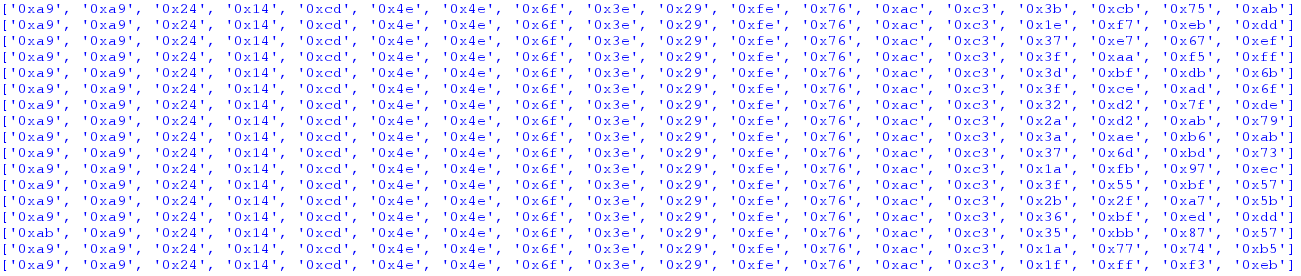
I have attached a screenshot showing the sort of thing I am receiving while the handset is trying to bind. As well as the 14 consistent bytes, it looks like the first 2 bits of the 15th byte are always 00. This may be part of the payload too.
As I didn't know the length of the payload I was looking for (and DPL was disabled), I initially over-guessed the length as 18 (and set this in RX_PW_P0). After the consistent bytes, the subsequent data seems to be nonsense (see screenshot). This suggests that the payload length is around 14.
Anyway - it looks like the CRC was preventing me from receiving any packets before - this is strange because apparently the BK2421 and nRF24 have the same 'enhanced shockburst' packet format. Any idea how I might be able to interpret the packets I received above?
Thanks!
I tried changing my nRF24L01 to operate in a 'stripped back' mode where CRC, Auto-Ack, Dynamic Payload, etc... are disabled and I have finally been able to detect signals. I tried listening on both addresses, (55, 42, 9C, 8F, C9) and (A9, 6F, A7, 91, B3), on the base binding channel (60) and I found that the handset is continually transmitting on both while it is trying to bind with the drone. I haven't interpreted the data yet, but it seems like each payload contains 14 consistent bytes which are continually transmitted.
I have attached a screenshot showing the sort of thing I am receiving while the handset is trying to bind. As well as the 14 consistent bytes, it looks like the first 2 bits of the 15th byte are always 00. This may be part of the payload too.
As I didn't know the length of the payload I was looking for (and DPL was disabled), I initially over-guessed the length as 18 (and set this in RX_PW_P0). After the consistent bytes, the subsequent data seems to be nonsense (see screenshot). This suggests that the payload length is around 14.
Anyway - it looks like the CRC was preventing me from receiving any packets before - this is strange because apparently the BK2421 and nRF24 have the same 'enhanced shockburst' packet format. Any idea how I might be able to interpret the packets I received above?
Thanks!
Please Log in or Create an account to join the conversation.
- hexfet
-
- Offline
Less
More
15 Oct 2016 17:59 - 15 Oct 2016 23:21 #54984
by hexfet
Replied by hexfet on topic Binding with my micro-drone
The comments in the binding sequence document about unknown registers and operations that make no sense are typical of the toy protocols. Fun to speculate about the firmware's origin, but it doesn't matter much. Generally we take the approach of duplicating the stock tx behavior as closely as possible.
The Addr1 is the bind address. All aircraft using this protocol will listen on this address, on the bind RF channel. Addr2 is the data address. The tx sends this address to the quad to bind, then switches to use that address for the data phase. This address will be different for every transmitter to reduce interference when multiple aircraft of the same protocol fly together. The other bytes sent in the bind packet may control the RF channels used in the data phase for the same reason. A large part of reverse-engineering a protocol often is figuring out the relationship between bind data and address/rf channels used. Here the address is sent directly.
Something doesn't quite add up about your bind description as I don't see a way for the tx to receive an ack when not sending on the bind address, but I didn't look at the SPI so maybe I'm misunderstanding. I can't remember which of the protocols we did that also sends to the data address for a while, before sending a single real bind packet to the bind address.
Last edit: 15 Oct 2016 23:21 by hexfet.
Please Log in or Create an account to join the conversation.
- george7378
-
16 Oct 2016 10:39 #55002
by george7378
Replied by george7378 on topic Binding with my micro-drone
Hey Hexfet - thanks very much for the reply That's helpful - I don't know much about protocol decoding (i.e. I know nothing about it) so it's encouraging that some of the bind messages are easy to understand.
I've actually made a bit more headway regarding the binding transmissions. I set my nRF24 running in 'promiscuous mode' as suggested in this blog post and after filtering out noise, I have found that the transmitter is actually sending on BOTH channels during the entire bind process, contrary to what the SPI seems to be showing. Here's a snapshot of what I'm seeing while the transmitter is binding:
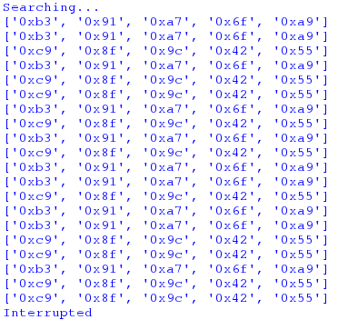
I have filtered out the rest of the message and I'm showing the addresses only. As you can see, there are regular occurrences of BOTH addresses (they are backwards because the LSByte is written first when they are entered into the chip registers).
Now to decode the message contents and see if they comply with what is being transmitted on SPI Thanks again, I'm happy now that I'm making progress! Still not entirely sure why I couldn't receive these messages with CRC enabled though.
I've actually made a bit more headway regarding the binding transmissions. I set my nRF24 running in 'promiscuous mode' as suggested in this blog post and after filtering out noise, I have found that the transmitter is actually sending on BOTH channels during the entire bind process, contrary to what the SPI seems to be showing. Here's a snapshot of what I'm seeing while the transmitter is binding:
I have filtered out the rest of the message and I'm showing the addresses only. As you can see, there are regular occurrences of BOTH addresses (they are backwards because the LSByte is written first when they are entered into the chip registers).
Now to decode the message contents and see if they comply with what is being transmitted on SPI
Please Log in or Create an account to join the conversation.
- george7378
-
16 Oct 2016 11:44 #55005
by george7378
Replied by george7378 on topic Binding with my micro-drone
OK, so after decoding the data sniffed in promiscuous mode, I have found that the following packets are being transmitted, seemingly in parallel on both the binding and flying addresses:
- Sent on A9 (flying address):
Packet control: 001001000
(9 bytes payload, complies with no. of bytes sent on SPI)
Payload: [00101001, 10011010, 10011100, 10011100, 11011110, 01111100, 01010011, 11111100, 11101101]
[29, 9A, 9C, 9C, DE, 7C, 53, FC, ED]
(Different to the data sent on SPI)
CRC: [01011001 10000110]
[59, 86]
Remaining: [0111101, 11011010, 10111111, 01011011, 10111101, 01010100, 10110111, 10110111, 11110101, 01110110, 11101100, 11100101]
(This is noise overflow - I read 32 bytes because I didn't know how much data there would be per packet)
- Sent on 55 (binding address):
Packet control: Same as A9
Payload: Same as A9
CRC: [10101000, 10110001]
[A8, B1]
Remaining: [1111110, 01110111, 01011100, 11000111, 11101111, 01101111, 10110000, 10110110, 10001011, 00111110, 11011001, 11011011]
(This is noise overflow - I read 32 bytes because I didn't know how much data there would be per packet)
Very strange - the payloads don't match anything seen in the SPI log, except in length. Perhaps there's some sort of custom firmware running on the BK2421 chip which is modifying the payloads sent in via SPI so that they are different when transmitted? Has anyone seen this sort of thing before?
Thanks very much
Please Log in or Create an account to join the conversation.
- george7378
-
16 Oct 2016 15:26 - 16 Oct 2016 15:53 #55015
by george7378
Replied by george7378 on topic Binding with my micro-drone
Another observation - it looks like the BK2421 sends the preamble twice and the least significant byte of the address three times ... this could be an issue when trying to re-construct the messages on the nRF24L01. I think I will have to do it with Enhanced Shockburst off and try to build the packet control field and CRC myself as part of the payload! This will be interesting.
This also probably explains why I can't receive the packages with CRC enabled on the nRF. Perhaps I will have to rely on the handset to do binding and then I could try and send my own flying packets having calculated the CRC myself...
This also probably explains why I can't receive the packages with CRC enabled on the nRF. Perhaps I will have to rely on the handset to do binding and then I could try and send my own flying packets having calculated the CRC myself...
Last edit: 16 Oct 2016 15:53 by george7378.
Please Log in or Create an account to join the conversation.
- george7378
-
18 Oct 2016 14:25 #55100
by george7378
Replied by george7378 on topic Binding with my micro-drone
I was wondering if anyone has come across a chip before which:
a) Repeats parts of the address and preamble in the messages sent on-air
b) Sends totally different payloads on-air to those which are clocked in via SPI
The packets I see being clocked in on SPI during bind are similar to the ones mentioned in this protocol post:
www.deviationtx.com/forum/protocol-devel...does-not-ack-packets
I'd really like to figure out if anything is happening inside the chip to modify the SPI payloads for transmission.
Please Log in or Create an account to join the conversation.
- hexfet
-
- Offline
Less
More
- Posts: 1868
18 Oct 2016 23:38 #55122
by hexfet
Replied by hexfet on topic Binding with my micro-drone
I don't have the equipment to look at the on-air data, but there's nothing in
the datasheet
to suggest the BK2421 would be modifying payloads. I had a 2421 in my Devo 10 for quite a while and it was 100% compatible with yd717 and SymaX protocols.
Please Log in or Create an account to join the conversation.
- george7378
-
20 Oct 2016 19:11 #55226
by george7378
Replied by george7378 on topic Binding with my micro-drone
Yeah, there's no mention of stuff like this anywhere else. It definitely looks like SPI isn't telling the full story though, as the payloads are so different and even when the address is changed during binding, the nRF24 is picking up stuff on both the old AND new addresses.
I can also confirm that the 'modified' payloads I receive on the nRF do actually make sense - I stripped away the address and packet control field to watch the numbers while moving the sticks, and they respond in a perfectly meaningful way.
I've soldered breadboard wires to the bk2421 in the controller to see if I can hijack it and get the drone flying that way. Real shame as I was hoping for an elegant solution using the nRF.
Please Log in or Create an account to join the conversation.
- george7378
-
20 Oct 2016 21:33 - 20 Oct 2016 21:34 #55230
by george7378
Replied by george7378 on topic Binding with my micro-drone
Just another quick post to fully demonstrate the on-air data differences. This is what I see being sent on SPI for both zero throttle and full throttle:
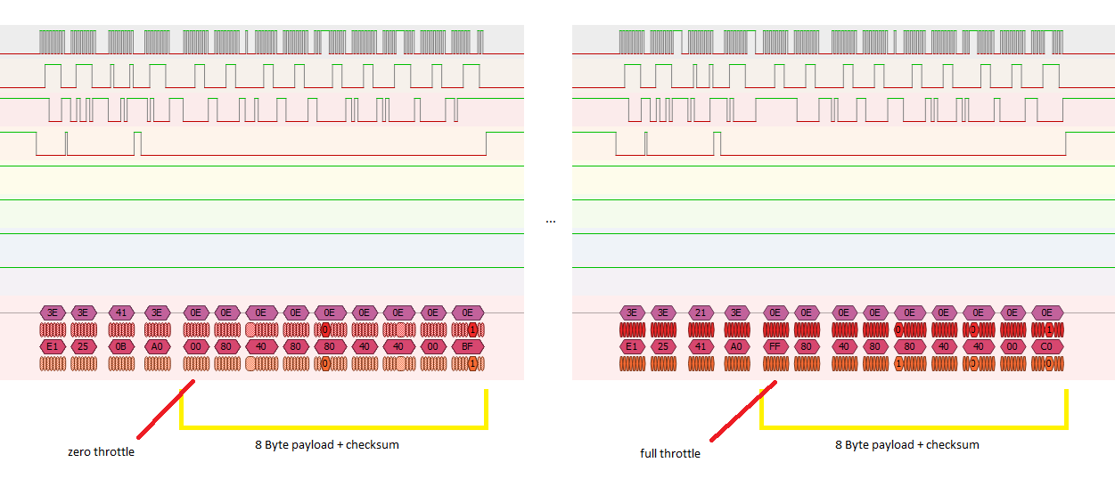
The clocked-in payload contains 8 flying data bytes (you can see that the throttle is the first byte) plus a one-byte checksum which I have worked out is calculated as follows:
255 - (sum_of_first_8_bytes)%256
...when I search on promiscuous mode with the nRF24, this is an example of a flying packet that I get:

The preamble byte appears at the beginning, suggesting that it has been repeated. Then the address, of which the least significant byte is repeated two extra times. Then the 9-bit packet control field, the payload and the 2-byte CRC.
When I strip back all the prior stuff and just print the payload followed by CRC, I see this:
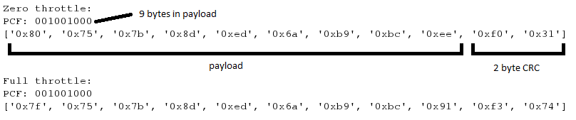
i.e. there are still 9 bytes, and the last one still seems to be a checksum while the others represent the same channels they do in the SPI payload above. However, the numbers themselves seem to have different ranges.
The most annoying part of this is the repeated preamble/address bytes because that totally throws off Enhanced Shuckburst and the ability to receive acks with the nRF24L01. The only way I can re-create these packets is to disable CRC and build them by fiddling the address, PCF and payload manually.
Perhaps someone will see this and know what's going on! Anyway, later on I will see if I have any success hijacking the BK2421.
The clocked-in payload contains 8 flying data bytes (you can see that the throttle is the first byte) plus a one-byte checksum which I have worked out is calculated as follows:
255 - (sum_of_first_8_bytes)%256
...when I search on promiscuous mode with the nRF24, this is an example of a flying packet that I get:
The preamble byte appears at the beginning, suggesting that it has been repeated. Then the address, of which the least significant byte is repeated two extra times. Then the 9-bit packet control field, the payload and the 2-byte CRC.
When I strip back all the prior stuff and just print the payload followed by CRC, I see this:
i.e. there are still 9 bytes, and the last one still seems to be a checksum while the others represent the same channels they do in the SPI payload above. However, the numbers themselves seem to have different ranges.
The most annoying part of this is the repeated preamble/address bytes because that totally throws off Enhanced Shuckburst and the ability to receive acks with the nRF24L01. The only way I can re-create these packets is to disable CRC and build them by fiddling the address, PCF and payload manually.
Perhaps someone will see this and know what's going on! Anyway, later on I will see if I have any success hijacking the BK2421.
Last edit: 20 Oct 2016 21:34 by george7378.
Please Log in or Create an account to join the conversation.
- george7378
-
21 Oct 2016 17:12 #55258
by george7378
Replied by george7378 on topic Binding with my micro-drone
I've solved two of the problems - i.e. the extra preamble byte and the issue of picking up binding messages on two different addresses. For my promiscuous mode I had clocked in the two-byte address in the wrong order (I forgot you had to do least significant byte first and never noticed the error). I also studied the binding procedure on SPI some more and discovered that it periodically switches between the two addresses and does about 60 transmissions on each.
Still standing are the issue with the repeated address byte and the fact that the payloads don't match what is seen on SPI. I doubt I will be able to find a solution for these though.
Still standing are the issue with the repeated address byte and the fact that the payloads don't match what is seen on SPI. I doubt I will be able to find a solution for these though.
Please Log in or Create an account to join the conversation.
Time to create page: 0.100 seconds
-
Home

-
Forum
-
Development
-
Protocol Development
- Binding with my micro-drone