
- Posts: 174
FY326 Q7 "red board"
- robca
-
Topic Author
- Offline
Less
More
30 Jun 2015 14:17 #34891
by robca
FY326 Q7 "red board" was created by robca
The FY326 has enjoyed a brief spurt of sales thanks to the good reviews of the original one (which at ~$27 was a great price). After the few initial units were sold with a "green board", it was found that it was compatible with the Syma protocol.
Unfortunately the FY326 is now sold with a red board, which is significantly worse than the green one, especially in Tx/Rx range. This is where Deviation could help.
I have a red board FY326, logic analyzer, USB scope, and various tools, and I'd be happy to help... I have no experience, though, in developing for Deviation nor in protocols. So I will need some help in getting started. Is there a "primer" on how to capture protocols?
Is anyone else already working on the FY326 red board protocol?
- Durete
-
- Offline
Less
More
- Posts: 610
30 Jun 2015 14:38 #34893
by Durete
Replied by Durete on topic FY326 Q7 "red board"
The original green board is working with YD717/Skywalker protocol, not Syma protocol. I don't have this quadcopter, so I can't help too much but I know an important information. The RX/TX is using a Beken BK2xxx family transceiver as the original green version, so I guess the protocol could be very similar to Skywalker protocol.
- robca
-
- Offline
Less
More
- Posts: 174
30 Jun 2015 15:24 #34899
by robca
Replied by robca on topic FY326 Q7 "red board"
Whoops, brain fart (on the green board protocol), thanks for the correction... I don't own one, so quoted from memory (obviously a bad idea... or more likely a bad memory ") )
)
At the time, I tried all the protocols suggested for the green one, none worked (and other people reported the same), so I know that even if similar, the red and green ones are not compatible. Hence my offer to help with the logic analyzer, if anyone can point me in the right direction
At the time, I tried all the protocols suggested for the green one, none worked (and other people reported the same), so I know that even if similar, the red and green ones are not compatible. Hence my offer to help with the logic analyzer, if anyone can point me in the right direction
- Richard96816
-
- Offline
Less
More
- Posts: 208
01 Jul 2015 10:02 #34933
by Richard96816
Replied by Richard96816 on topic FY326 Q7 "red board"
Too bad you can't decode the signal with a receiver instead of having to disassemble the transmitter and connect a logic analyzer. Like some old TV remotes that would record the signal from an individual function/key from the original remote and 'play it back' to control the TV.
I have a Q7. It would be great with Deviation.
I have a Q7. It would be great with Deviation.
- Durete
-
- Offline
Less
More
- Posts: 610
01 Jul 2015 10:10 #34934
by Durete
Replied by Durete on topic FY326 Q7 "red board"
You can snif SPI traces from both, TX and RX, but usually is easier to snif at TX side. Sometimes is required to snif also at RX side to "fine tune" the protocol.
- S.Giles
-
- Offline
Less
More
- Posts: 27
01 Jul 2015 10:53 - 01 Jul 2015 21:04 #34936
by S.Giles
Replied by S.Giles on topic FY326 Q7 "red board"
Hi,
I also have the 'red board' FY326 and have just ordered a logic analyser, but at the moment have only a vague idea how to use it. I'm aware that there are some data links between the microprocessor and transceiver which is where the data is accessible.
I would also be very interested in a protocol-decoding 'primer' to help me get started.
Steve
Last edit: 01 Jul 2015 21:04 by S.Giles. Reason: Irrelevancies removed
- Moeder
-
- Offline
Less
More
- Posts: 796
01 Jul 2015 14:12 #34944
by Moeder
Replied by Moeder on topic FY326 Q7 "red board"
Take a look at
this thread
for a start on how to setup SPI tracing. If you post a picture of the TX with the module we can most likely point you to the right signal pins to trace.
- Alias_Hendrik
-
- Offline
Less
More
- Posts: 51
01 Jul 2015 16:47 #34948
by Alias_Hendrik
Replied by Alias_Hendrik on topic FY326 Q7 "red board"
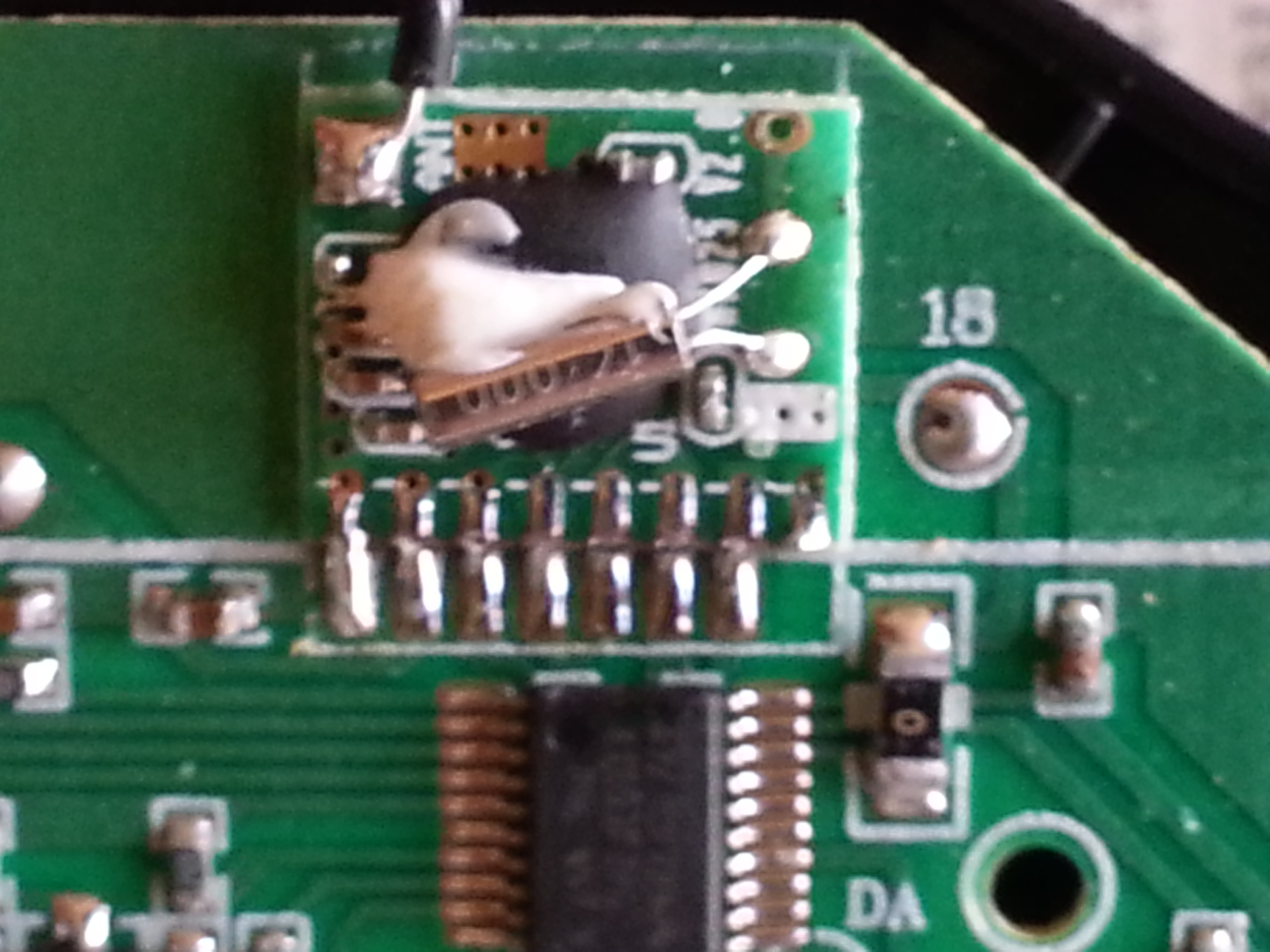
The FY-326 red board (board marking TS-FY01R) in the quad uses a Beken 2425 chip.
In the transmitter I can not read fully the number on tx board but it ends also with 25.
In the picture, the transmitter tx module, (crystal 16Mhz)
Pin naming, starting from the LEFT: GND / VCC / CE / CSN / CSK / Mosi / Miso / IRQ (not used).
(the pin names are written on the backside tx module and also on the other side from the mother board where the sticks are).
- SeByDocKy
-
- Offline
Less
More
- Posts: 1016
01 Jul 2015 17:21 #34951
by SeByDocKy
The BK2325 is 100% compatible with the nRF24L01
Replied by SeByDocKy on topic FY326 Q7 "red board"
Alias_Hendrik wrote: The FY-326 red board (board marking TS-FY01R) in the quad uses a Beken 2425 chip.
In the transmitter I can not read fully the number on tx board but it ends also with 25.
In the picture, the transmitter tx module, (crystal 16Mhz)
Pin naming, starting from the LEFT: GND / VCC / CE / CSN / CSK / Mosi / Miso / IRQ (not used).
(the pin names are written on the backside tx module and also on the other side from the mother board where the sticks are).
The BK2325 is 100% compatible with the nRF24L01
- Alias_Hendrik
-
- Offline
Less
More
- Posts: 51
01 Jul 2015 19:23 #34960
by Alias_Hendrik
Replied by Alias_Hendrik on topic FY326 Q7 "red board"
@ Seby
Yep and for fun I desoldered the module and put wires in place connected to an NRF + PA + LNA but that didn't work lol otherwise it was a cheap way to increase range. So i soldered the original module back in.
With original tx during bind, the tx is awaiting some sort of an acknowledge signal from the quad. As soon as the tx receives it I can arm the quad.
Anyway those that have the FY-326 red board and a logic analyzer can give it a try to capture with the mentioned pin designations in previous post.
- S.Giles
-
- Offline
Less
More
- Posts: 27
01 Jul 2015 19:29 #34961
by S.Giles
Does anyone have any idea why this did not work?
Replied by S.Giles on topic FY326 Q7 "red board"
I've been thinking about this attempt to replace the original transceiver with the NRF module since reading that they should be compatible this afternoon.Alias_Hendrik wrote: @ Seby
Yep and for fun I desoldered the module and put wires in place connected to an NRF + PA + LNA but that didn't work lol otherwise it was a cheap way to increase range. So i soldered the original module back in.
Does anyone have any idea why this did not work?
- Durete
-
- Offline
Less
More
- Posts: 610
01 Jul 2015 20:15 #34962
by Durete
Maybe that's could be the reason to not work.
Replied by Durete on topic FY326 Q7 "red board"
Did you try bridging VCC with CE (chip enable) at nRF module?Alias_Hendrik wrote: @ Seby
Yep and for fun I desoldered the module and put wires in place connected to an NRF + PA + LNA but that didn't work lol otherwise it was a cheap way to increase range. So i soldered the original module back in.
With original tx during bind, the tx is awaiting some sort of an acknowledge signal from the quad. As soon as the tx receives it I can arm the quad.
Anyway those that have the FY-326 red board and a logic analyzer can give it a try to capture with the mentioned pin designations in previous post.
Maybe that's could be the reason to not work.
- Alias_Hendrik
-
- Offline
Less
More
- Posts: 51
01 Jul 2015 21:06 #34964
by Alias_Hendrik
Replied by Alias_Hendrik on topic FY326 Q7 "red board"
Thought about it but didn't do it because the CE was connected to the MCU and that way it would take care of tx/rx like with original module. I think it has something to do with that, the quad sends a signal back. With the NRF in place, the led on the tx was blinking, meaning it is waiting for a signal from the quad.
- Durete
-
- Offline
Less
More
- Posts: 610
01 Jul 2015 21:29 #34965
by Durete
Uppssss... Sorry, I missed that. If the CE signal from nRF module is used/connected to the MCU at the TX, should not be needed.
Replied by Durete on topic FY326 Q7 "red board"
Alias_Hendrik wrote: Thought about it but didn't do it because the CE was connected to the MCU and that way it would take care of tx/rx like with original module. I think it has something to do with that, the quad sends a signal back. With the NRF in place, the led on the tx was blinking, meaning it is waiting for a signal from the quad.
Uppssss... Sorry, I missed that. If the CE signal from nRF module is used/connected to the MCU at the TX, should not be needed.
- robca
-
- Offline
Less
More
- Posts: 174
02 Jul 2015 09:59 #34976
by robca
Replied by robca on topic FY326 Q7 "red board"
Thanks everyone for the super detailed info, I captured a few traces, please let me know if they do not work. I used 8MHz sampling rate, and connected the wires as follows:
0 CSN
1 CSK
2 MOSI
3 MISO
4 CE (which I don't think was needed, but it cost nothing to add it)
I captured two series of traces, which I called Full and Short. Full goes thru the whole startup process: bind, arm (throttle from 0 to 100 then back to 0), followed by the channel sequence suggested by Phracturedblue (below)
As a result I captured a few binding sequences over a few minutes, as suggested
The Short traces are captured with the FY326 already bound and armed, just going thru the channels (I captured the only switch available, right joystick pressed in, in the short traces, I forgot to do it in the long traces)
I exported the traces both as the native Saleae format and CSV, and as a result the files are pretty big. I uploaded them on OneDrive, here: 1drv.ms/1FU1Tzs , open to everyone as read only
Please let me know if there's anything else I can do to help
0 CSN
1 CSK
2 MOSI
3 MISO
4 CE (which I don't think was needed, but it cost nothing to add it
I captured two series of traces, which I called Full and Short. Full goes thru the whole startup process: bind, arm (throttle from 0 to 100 then back to 0), followed by the channel sequence suggested by Phracturedblue (below)
We need to capture the following (each as a separate trace ideally, but it can be in one if you keep track of the order)
1) power on and binding
2) throttle (0 - 100 - 0)
3) elevator (50 - 0 - 50 - 100 - 0)
4) aileron (50 - 0 - 50 - 100 - 0)
5) rudder (50 - 0 - 50 - 100 -0)
6) any buttons/switches on the Tx, one at a time
As a result I captured a few binding sequences over a few minutes, as suggested
The Short traces are captured with the FY326 already bound and armed, just going thru the channels (I captured the only switch available, right joystick pressed in, in the short traces, I forgot to do it in the long traces)
I exported the traces both as the native Saleae format and CSV, and as a result the files are pretty big. I uploaded them on OneDrive, here: 1drv.ms/1FU1Tzs , open to everyone as read only
Please let me know if there's anything else I can do to help
- Durete
-
- Offline
Less
More
- Posts: 610
04 Jul 2015 16:15 - 04 Jul 2015 20:53 #35105
by Durete
Replied by Durete on topic FY326 Q7 "red board"
The throttle channel has a big jump (from 00 to 14) at low end of throttle stick (channel goes from 00 to C8)
Here is the "infamous" throttle dropout on this Quadcopter
The CSV files are useless, because Robca forgot to add an SPI analyzer at Salea software. The Session files needs to be "tweaked" to export again the CSV files.
Here is what I found:
This is my first time, I'm trying to learn to decode the captures, please excuse me if i'm wrong
Edit. BTW, I'm not a developer, and my programming skills are very limited (even worse, I don't have programming skills at all ), so I can't program a protocol implementation. I'm only trying to learn to decode the SPI captures.
1.155841   > TX_PYLD_NOACK       b0 90 00 64 64 64 00 aa a3 cb 00 00 00 00 90 1c => 2e 00 00 00 00 00 00 00 00 00 00 00 00 00 00 00
1.157234   > RF_CH               25 15                                    => 2e 00
1.157266   = FLUSH_TX            e1 00                                    => 2e 2e
1.157293   < CONFIG              00 00                                    => 2e 0e
1.157320   > CONFIG              20 0e                                    => 2e 00
1.157348   < FIFO_STATUS         17 00                                    => 2e 11
1.157375   < STATUS              07 00                                    => 2e 2e
1.157402   < STATUS              07 00                                    => 2e 2e
1.157433   > TX_PYLD_NOACK       b0 90 00 64 64 64 14 aa a3 cb 00 00 00 00 90 1c => 2e 00 00 00 00 00 00 00 00 00 00 00 00 00 00 00
Here is the "infamous" throttle dropout on this Quadcopter
The CSV files are useless, because Robca forgot to add an SPI analyzer at Salea software. The Session files needs to be "tweaked" to export again the CSV files.
Here is what I found:
Bind packet: 90 55 00 00 00 00 50 a3 cb 00 00 00 00 aa 1c
Data phase TX address: 2a 15 59 23 c6 29
Bind at channel 17
RF channels 00 15 23 3a 4b
Throttle 5° byte from 00 to C8 (jump from 00 to 14)
Elevator 3° byte from 00 to C8 (64 center)
Aileron  2° byte from 00 to C8 (64 center)
Rudder   4° byte from 00 to C8  (64 center)
This is my first time, I'm trying to learn to decode the captures, please excuse me if i'm wrong
Edit. BTW, I'm not a developer, and my programming skills are very limited (even worse, I don't have programming skills at all
Last edit: 04 Jul 2015 20:53 by Durete.
- Richard96816
-
- Offline
Less
More
- Posts: 208
05 Jul 2015 22:16 #35138
by Richard96816
Replied by Richard96816 on topic FY326 Q7 "red board"
Nice to see folks working on the Q7. Took mine out to an open field last night, after extending it's antenna wire through an existing hole in the top of the case. Seems to work better now, but range is still somewhat limited. The dropout problem does seem to be exacerbated by range, or lack of it.
Will be interested to hear how similar the protocols are. If they just changed some chips it might be very similar. Hopefully they didn't break something that's not easy to fix with a protocol tweak or a little more transmitter power. It is, otherwise a nice quad, with lots of potential.
I may have to get a logic analyzer. So many quads ...
- S.Giles
-
- Offline
Less
More
- Posts: 27
10 Jul 2015 21:20 - 11 Jul 2015 09:33 #35311
by S.Giles
Replied by S.Giles on topic FY326 Q7 "red board"
I have also made some 'red board' FY326 captures. They can be accessed
here
.
To complement robca's captures, flips, expert mode, and the trim buttons in addition to another bind sequence have been included.
I have a 'guinea pig' FY326 TX set up for data capture, so can easily add anything more that may become necessary.
To complement robca's captures, flips, expert mode, and the trim buttons in addition to another bind sequence have been included.
I have a 'guinea pig' FY326 TX set up for data capture, so can easily add anything more that may become necessary.
Last edit: 11 Jul 2015 09:33 by S.Giles.
- hexfet
-
- Offline
Less
More
- Posts: 1971
13 Jul 2015 22:27 - 13 Jul 2015 22:56 #35413
by hexfet
It's a two-way bind protocol, but doesn't look like anything is received from the aircraft after binding. In this data the relevant values are:
Seems like only the RF channels change based on the transmitter specific data in the bind packet (the "txid"), or possibly based on the info returned from the aircraft. Need to figure out that relationship.
The last couple bytes seem to be fixed, not a checksum.
Replied by hexfet on topic FY326 Q7 "red board"
I've looked at the bind sequence in this data. In future please export the decoded SPI data to CSV (click on the SPI settings icon to export) as this is the format expected by the decoding scripts.S.Giles wrote: I have also made some 'red board' FY326 captures. They can be accessed here .
It's a two-way bind protocol, but doesn't look like anything is received from the aircraft after binding. In this data the relevant values are:
RX/TX address: 15 59 23 c6 29  (Same address for bind and data phases.  Three-byte address width so only last three bytes used.)
TX bind packet: d9 55 00 00 00 00 62 9a ff 00 00 00 00 aa 23
RX bind packet: d9 55 00 00 00 00 aa 9a ff 00 00 00 00 9e 23
Data phase RF channels: 02, 16, 2a, 39, 4f
Seems like only the RF channels change based on the transmitter specific data in the bind packet (the "txid"), or possibly based on the info returned from the aircraft. Need to figure out that relationship.
The last couple bytes seem to be fixed, not a checksum.
Last edit: 13 Jul 2015 22:56 by hexfet.
- hexfet
-
- Offline
Less
More
- Posts: 1971
14 Jul 2015 02:11 - 20 Jul 2015 16:06 #35420
by hexfet
Replied by hexfet on topic FY326 Q7 "red board"
Below is what I have for the data packet format based on SGiles captures. Anyone else see something different?
The throttle channel "jump" also appears on the 3-axis controls - and on both sides of the center value. The jump has magnitude 20, which is also the range of the trim values. Maybe the receiver just adds them together to get a final value...but changes sign based on which side of the center value? and why not just add them on the tx? (Speculating "why?" with these protocols seems useless) Is the jump on the roll, pitch, and yaw controls noticeable when flying? maybe a dead-zone around center stick?
In one capture (expert mode yaw) bit 4 of byte one is set. Is there a third "control" besides expert mode and flips?
byte
0  - 0xD9
1  - b0: calibrate
     b1: flip
     b2: expert
     b6: return-to-home (back up)
     b7: headless
2  - roll,  0x64 center, 0x78-0xc8 right,   0x50-0x00 left
3  - pitch, 0x64 center, 0x78-0xc8 forward, 0x50-0x00 backward
4  - yaw,   0x64 center, 0x78-0xc8 right,   0x50-0x00 left
5  - throttle
6  - 0xAA
7  - 0x9A
8  - 0xFF
9  - roll trim,     -20 to +20, positive right
10 - pitch trim,    -20 to +20, positive up
11 - yaw trim,      -20 to +20, positive right
12 - throttle trim, -20 to +20, positive up
13 - 0x9E
14 - 0x23
Last edit: 20 Jul 2015 16:06 by hexfet.
Time to create page: 0.290 seconds
-
Home

-
Forum
-
Development
-
Protocol Development
- FY326 Q7 "red board"