
- Posts: 2
Help Solder point on nRF24L01
- Urrtoast
-
Topic Author
- Offline
Less
More
01 Jan 2015 04:42 - 01 Jan 2015 04:47 #27394
by Urrtoast
Help Solder point on nRF24L01 was created by Urrtoast
HI There
My 1st post
I am new to the whole Heli quad world but would like to purchase a Devo 7e and mod it with a nRF24L01+pwramp
www.banggood.com/2_4G-NRF24L01-PA-LNA-Wi...ntenna-p-922601.html
or
www.banggood.com/DEVO-Transmitter-Tuner-...ys-V922-p-89812.html im guessing its the same item.
In this picture it shows Red VCC and Pink CE being soldered to the same spot on the Devo Board VDD Is this correct.?
Thanks in advance
Last edit: 01 Jan 2015 04:47 by Urrtoast.
- SeByDocKy
-
- Offline
Less
More
- Posts: 1016
01 Jan 2015 08:09 #27396
by SeByDocKy
Right
Replied by SeByDocKy on topic Help Solder point on nRF24L01
Urrtoast wrote: HI There
My 1st post
I am new to the whole Heli quad world but would like to purchase a Devo 7e and mod it with a nRF24L01+pwramp
www.banggood.com/2_4G-NRF24L01-PA-LNA-Wi...ntenna-p-922601.html
or
www.banggood.com/DEVO-Transmitter-Tuner-...ys-V922-p-89812.html im guessing its the same item.
In this picture it shows Red VCC and Pink CE being soldered to the same spot on the Devo Board VDD Is this correct.?
Thanks in advance
Right
- Urrtoast
-
- Offline
Less
More
- Posts: 2
01 Jan 2015 08:25 #27397
by Urrtoast
Replied by Urrtoast on topic Help Solder point on nRF24L01
Cheers Thanks for the quick answer
Happy New Yrs )
)
Happy New Yrs
- voyn
-
- Offline
Less
More
- Posts: 50
02 Jan 2015 23:24 #27424
by voyn
Replied by voyn on topic Help Solder point on nRF24L01
I just installed the NRF24L01 in my Devo 8S today, but I'm not convinced I did it right. Here are the connections I made from the RF module to the transmitter:
Pin 1 -> GND point on main board (near VCC and TCK)
Pin 2 -> VCC
Pin 3 -> jumpered to NRF24L01 pin 2
Pin 4 -> TCK (I already have the A7105 connected to TMS)
Pin 5 -> CYRF pin 2 (SCK)
Pin 6 -> CYRF pin 4 (MOSI)
Pin 7 -> CYRF pin 5 (MISO)
Pin 8 -> not connected
I also edited the hardware.ini file to enable the chip and show that it has the power amplifier built in. I made a model profile based on my Hubsan profile, but changed it to SLT protocol. I also made another profile from scratch using the SLT protocol.
As near as I can tell, everything is connected correctly. My A7105 module still controls my Hubsan quads (so I don't think I screwed anything up too badly), but when I tried to bind to my Dromida Ominus using the SLT protocol, it binds but does not behave properly.
The lights flashed as if it were bound but nothing happened until I put the throttle to 100%, then it went straight up in the air and would not stop even when I put the throttle all the way back to -100. Luckily I was inside and was able to bat it out of the air and disconnect the battery (oww my poor fingers - I've since removed the props") )
)
Since this is my first experience with both creating my own model profile and the NRF24L01, I'm not sure how to proceed. Any ideas, anyone?
Pin 1 -> GND point on main board (near VCC and TCK)
Pin 2 -> VCC
Pin 3 -> jumpered to NRF24L01 pin 2
Pin 4 -> TCK (I already have the A7105 connected to TMS)
Pin 5 -> CYRF pin 2 (SCK)
Pin 6 -> CYRF pin 4 (MOSI)
Pin 7 -> CYRF pin 5 (MISO)
Pin 8 -> not connected
I also edited the hardware.ini file to enable the chip and show that it has the power amplifier built in. I made a model profile based on my Hubsan profile, but changed it to SLT protocol. I also made another profile from scratch using the SLT protocol.
As near as I can tell, everything is connected correctly. My A7105 module still controls my Hubsan quads (so I don't think I screwed anything up too badly), but when I tried to bind to my Dromida Ominus using the SLT protocol, it binds but does not behave properly.
The lights flashed as if it were bound but nothing happened until I put the throttle to 100%, then it went straight up in the air and would not stop even when I put the throttle all the way back to -100. Luckily I was inside and was able to bat it out of the air and disconnect the battery (oww my poor fingers - I've since removed the props
Since this is my first experience with both creating my own model profile and the NRF24L01, I'm not sure how to proceed. Any ideas, anyone?
- voyn
-
- Offline
Less
More
- Posts: 50
03 Jan 2015 20:22 #27440
by voyn
Replied by voyn on topic Help Solder point on nRF24L01
Nevermind, sorted it out. Despite what the manual said about SLT compatibility, I figured out I had to reverse every single control channel. Now it works great! I did relocate the NRF24L01's GND connection to the Devo's CYRF module before I reversed everything, but I don't think it made any difference.
- aMax
-
- Offline
Less
More
- Posts: 776
03 Jan 2015 20:37 #27443
by aMax
Devo7e, TaranisQ X7, R9M , 4in1 MM, Futaba FC18plusV3.2 & DFT/FLD-02
Replied by aMax on topic Help Solder point on nRF24L01
No difference. My GND connection for this module goes to the shield ground.
Devo7e, TaranisQ X7, R9M , 4in1 MM, Futaba FC18plusV3.2 & DFT/FLD-02
- voyn
-
- Offline
Less
More
- Posts: 50
03 Jan 2015 20:42 #27445
by voyn
Replied by voyn on topic Help Solder point on nRF24L01
Yeah, that's kind of what I figured. Realized it was probably the exact same point electrically speaking, but relocated it just in case it had to be on the CYRF module for some mystical reason. I could have gotten the meter from the car and checked, but it's cold and rainy out and the soldering iron was sitting right there in easy reach ")
- aMax
-
- Offline
Less
More
- Posts: 776
04 Jan 2015 01:11 - 04 Jan 2015 01:20 #27452
by aMax
Devo7e, TaranisQ X7, R9M , 4in1 MM, Futaba FC18plusV3.2 & DFT/FLD-02
Replied by aMax on topic Help Solder point on nRF24L01
Two extra modules installed.
One connected at the modul pcb, the nRF is connected to
the main pcb. GND for this left shielding joint. No issues so far.
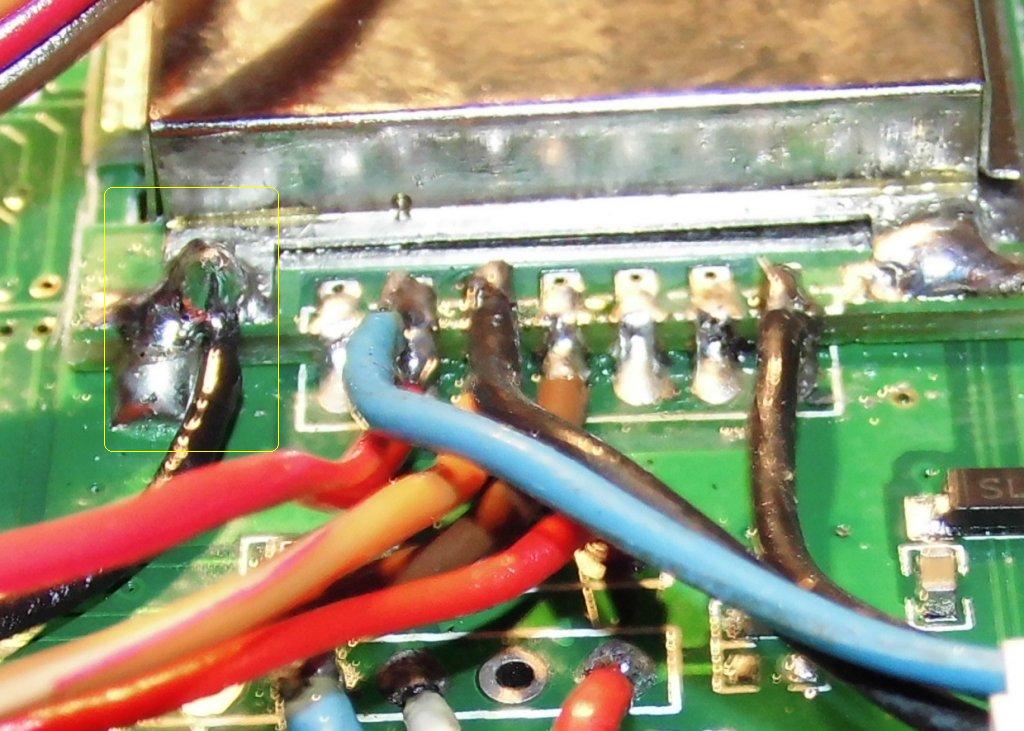
Don´t mind the space between shield and modul pcb, it´s already reworked.
One connected at the modul pcb, the nRF is connected to
the main pcb. GND for this left shielding joint. No issues so far.
Don´t mind the space between shield and modul pcb, it´s already reworked.
Devo7e, TaranisQ X7, R9M , 4in1 MM, Futaba FC18plusV3.2 & DFT/FLD-02
Last edit: 04 Jan 2015 01:20 by aMax.
- hansman007
-
- Offline
Less
More
- Posts: 10
24 Jan 2015 16:41 - 24 Jan 2015 17:08 #27968
by hansman007
Replied by hansman007 on topic Help Solder point on nRF24L01
Hi,
this is my first Post here.
Got my nRF24L01 working with the help of this thread. Thanks for that!
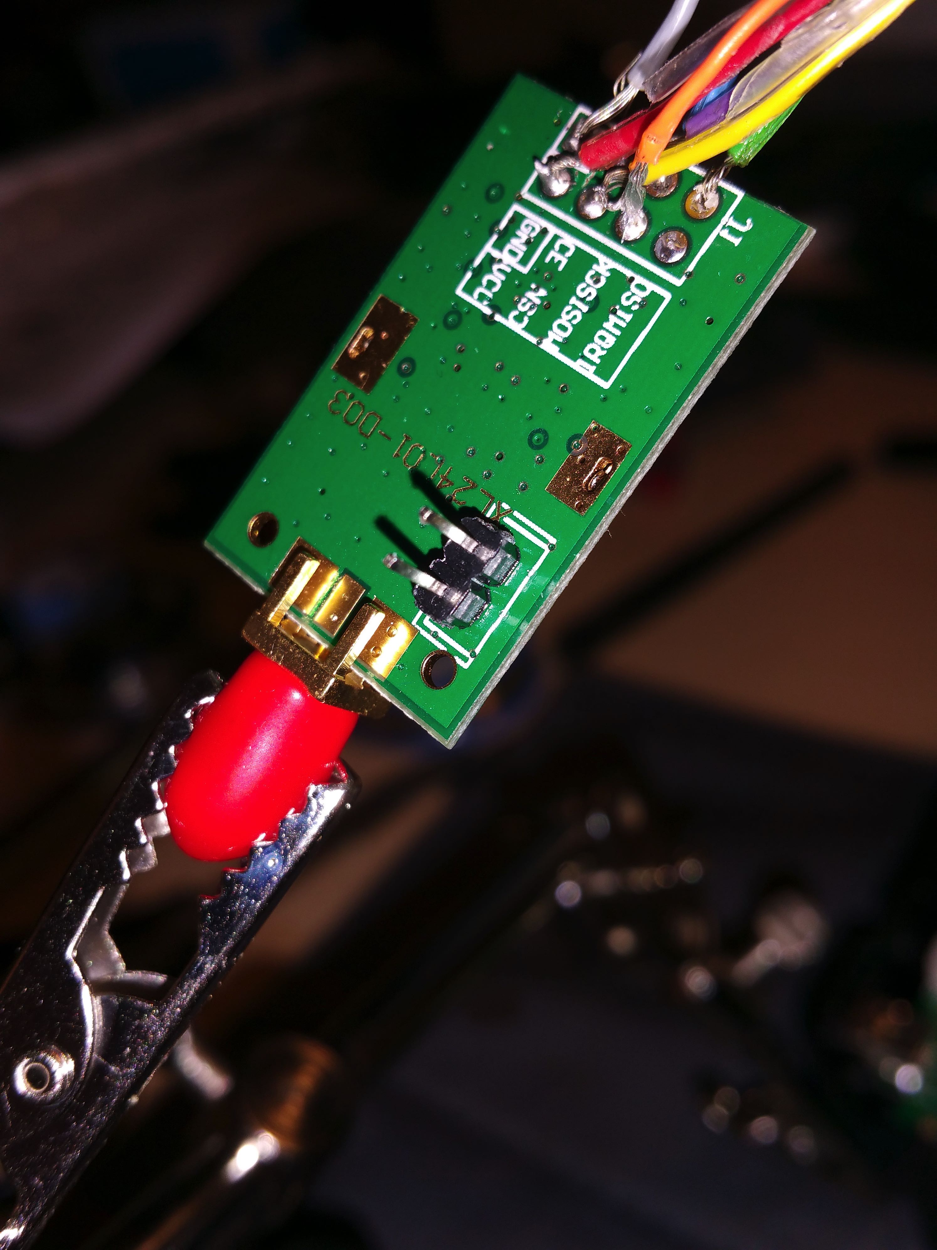
My module has 2 additional pins. See Photo.
What are these for?
Thanks in advance...
Hansman
this is my first Post here.
Got my nRF24L01 working with the help of this thread. Thanks for that!
My module has 2 additional pins. See Photo.
What are these for?
Thanks in advance...
Hansman
Last edit: 24 Jan 2015 17:08 by hansman007.
- Arakon
-
- Offline
Less
More
- Posts: 305
24 Jan 2015 17:29 #27970
by Arakon
Replied by Arakon on topic Help Solder point on nRF24L01
I don't know about the pins, but please redo your soldering job. With the blank wires open like this, you have a very high chance of a short and destroying the module and/or the radio. Keep the blank end very short so all of the blank wire ends up attached to the solder point.
- voyn
-
- Offline
Less
More
- Posts: 50
24 Jan 2015 17:51 #27971
by voyn
Replied by voyn on topic Help Solder point on nRF24L01
Yikes, yeah, don't use that module as it is. There's way too much exposed wire on almost all of those connections. You're bound to fry something sooner or later.
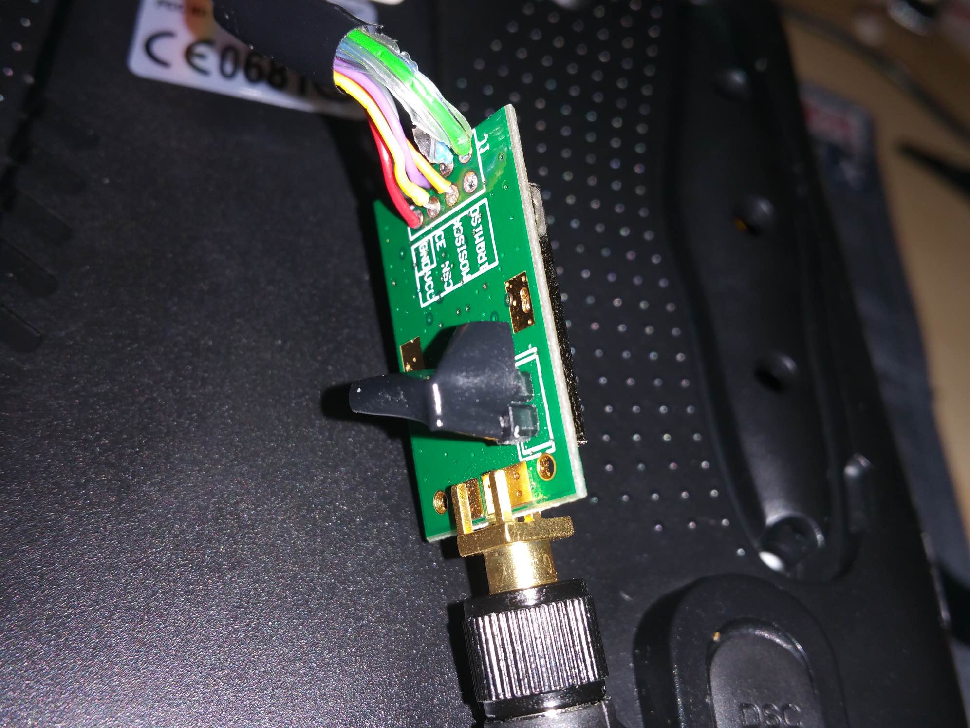
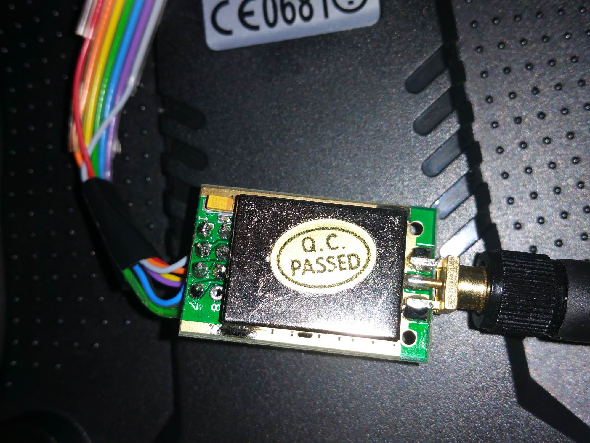
As for those two pins - no idea. What does the other side of the board say? Are they labelled in any way?
As for those two pins - no idea. What does the other side of the board say? Are they labelled in any way?
- hansman007
-
- Offline
Less
More
- Posts: 10
24 Jan 2015 18:16 #27972
by hansman007
Replied by hansman007 on topic Help Solder point on nRF24L01
Hi,
already did the resoldering
says nothing...
is covered with housing
already did the resoldering
says nothing...
is covered with housing
- voyn
-
- Offline
Less
More
- Posts: 50
24 Jan 2015 18:31 #27973
by voyn
Replied by voyn on topic Help Solder point on nRF24L01
Hoo-boy, that looks much better 
As for those two pins, as long as everything is working well: correct function, good range... I wouldn't worry about it too much.
As for those two pins, as long as everything is working well: correct function, good range... I wouldn't worry about it too much.
- hansman007
-
- Offline
Less
More
- Posts: 10
24 Jan 2015 18:49 #27974
by hansman007
Replied by hansman007 on topic Help Solder point on nRF24L01
My solder training in school was 1997...
but its coming back slowly.
Yes module works an I used your model.ini for the Dromida ominus quad.
Used it on my Devo 7e. Thanks for that by the way!
works so far... still sorting out the switch thing cause of the missing switches on the 7e.
but its coming back slowly.
Yes module works an I used your model.ini for the Dromida ominus quad.
Used it on my Devo 7e. Thanks for that by the way!
works so far... still sorting out the switch thing cause of the missing switches on the 7e.
- voyn
-
- Offline
Less
More
- Posts: 50
24 Jan 2015 19:17 #27976
by voyn
Replied by voyn on topic Help Solder point on nRF24L01
Yeah I had to resolder mine a few times to get it where I wanted it, hehe.
I'm glad the Ominus .ini file is working for you! With all this kind of stuff (quad mods, Android/iOS hacks, etc) I usually just implement things that other people have already worked hard to figure out. It's nice to give back, even just a little bit.
Which switches are missing on the 7E? If you tell me the ones you want to use, maybe I can re-map them to the corresponding switches on the 8S (assuming I have them too). Since the 7E is so popular, it would probably be a good idea anyways.
- mwm
-
- Offline
24 Jan 2015 22:48 - 24 Jan 2015 22:48 #27982
by mwm
This is a common problem. While the 6 isn't quite as popular, it has similar problems. And those working on a 12 have more than anyone.
I decided we needed some documentation on this, so I wrote it.
Do not ask me questions via PM. Ask in the forums, where I'll answer if I can.
My remotely piloted vehicle ("drone") is a yacht.
Replied by mwm on topic Help Solder point on nRF24L01
voyn wrote: Which switches are missing on the 7E? If you tell me the ones you want to use, maybe I can re-map them to the corresponding switches on the 8S (assuming I have them too). Since the 7E is so popular, it would probably be a good idea anyways.
This is a common problem. While the 6 isn't quite as popular, it has similar problems. And those working on a 12 have more than anyone.
I decided we needed some documentation on this, so I wrote it.
Do not ask me questions via PM. Ask in the forums, where I'll answer if I can.
My remotely piloted vehicle ("drone") is a yacht.
Last edit: 24 Jan 2015 22:48 by mwm. Reason: Damn ENTER-on-URL-Insert
- aMax
-
- Offline
Less
More
- Posts: 776
25 Jan 2015 00:27 #27986
by aMax
Devo7e, TaranisQ X7, R9M , 4in1 MM, Futaba FC18plusV3.2 & DFT/FLD-02
Replied by aMax on topic Help Solder point on nRF24L01
Why is it complicated to install two three-way instead of two two-way switches?
If you choose three-way, you have exact the same amount of switches as the Devo6.
If you choose three-way, you have exact the same amount of switches as the Devo6.
Devo7e, TaranisQ X7, R9M , 4in1 MM, Futaba FC18plusV3.2 & DFT/FLD-02
- mwm
-
- Offline
25 Jan 2015 00:58 #27990
by mwm
Do not ask me questions via PM. Ask in the forums, where I'll answer if I can.
My remotely piloted vehicle ("drone") is a yacht.
Replied by mwm on topic Help Solder point on nRF24L01
The Devo7e uses a less expensive microcontroller with fewer inputs and less memory than the rest of the Devo transmitters. This is why you protocols are split loaded at run time instead of being part of the dfu for the 7e build.
There are exactly two unused inputs on the 7e microcontroller. The obvious thing to do is connecting two 2-ways switches, so each one is either on or off. Because there are already two 2-way switches on the 7e, some (like me) would rather have a single 3-way switch. That's still just connecting things up properly - they are either both off, or one or the other is on.
To get two 3-way switches, you have to add some diodes so you get three states on each of two inputs. I'm fuzzy on the details, as I sold my 7e and bought a 6s before this one was published.
Because the 6 uses the same hardware as the 8, you should be able to add switches or analog inputs to it. I don't know that anyone has looked into it, and may do so myself at some point.
Do not ask me questions via PM. Ask in the forums, where I'll answer if I can.
My remotely piloted vehicle ("drone") is a yacht.
- mwm
-
- Offline
25 Jan 2015 01:03 - 25 Jan 2015 08:12 #27991
by mwm
Do not ask me questions via PM. Ask in the forums, where I'll answer if I can.
My remotely piloted vehicle ("drone") is a yacht.
Replied by mwm on topic Help Solder point on nRF24L01
The devo7e uses a less expensive cpu than the rest of the Devo transmitters. It has less memory, which is why protocols are loaded dynamically instead of being part of the dfu. But it also has fewer inputs.
There are exactly two unused spots available in the 7e button matrix. Adding two two-way switches is easy: you just wire each switch to the right spot and a positive signal. Because there are already two 2-way switches, some people would prefer a 3-way switch. Still easy: you wire the switch to an on signal, and then the two outputs to the two available spots. So either both inputs are off, or one of them is on.
I'm fuzzy on the two 3-way switch mod, as I sold my 7e and bought a 6s before it was published. I haven't been able to turn up the directions for it, but recall it needing more parts than the 2x2 or 1x3 mods.
Since the 6s uses the same hardware as the 8, you ought to be able to add switches to it a well. I don't know if anyone has looked into this. I'm planning on doing it at some point, but it's low on my priority list.
Do not ask me questions via PM. Ask in the forums, where I'll answer if I can.
My remotely piloted vehicle ("drone") is a yacht.
Last edit: 25 Jan 2015 08:12 by mwm. Reason: Correct outdated info
- hansman007
-
- Offline
Less
More
- Posts: 10
25 Jan 2015 09:09 #28004
by hansman007
Replied by hansman007 on topic Help Solder point on nRF24L01
@voyn
I merged your file and the ultra beginners file for walkera cp helis from Tom Z and yours for the Ominus.
strange thing with your file was that the drone was drifting and the trim was not working.
so I used the trim part from tom Zs file.
the motor safety is perfect for avoiding damage. I only have one Fmod so thats the main issue.
I already orderd the parts for 2 3way switches. Seems pretty easy regarding the soldering.
Regarding the Software... thats the hard part for me... which switch ID goes where in the model ini.
P.S.: forgive me my bad english... I'm from Germany
Time to create page: 0.591 seconds
-
Home

-
Forum
-
General
-
General Discussions
- Help Solder point on nRF24L01