
Extra inputs for Devo Tx's
- robocog
-
- Offline
Less
More
01 Aug 2015 17:45 #36441
by robocog
Replied by robocog on topic Extra inputs for Devo Tx's
I bought a couple of them...just in case I get the bug (or screw up the soldering)...and for the price
I do need the DSC port in a working state for DRM purposes so am VERY interested in your findings
I have also been thinking about current draw - as its only the occasional model that will actually have a use of a twiddly knob
I /may/ use it as an external device - with a flying jack lead and seperate power lead to attach it to the radio (eg only when needed)
Am I right in thinking that the 2 TX modules I have installed (NRF and A7105) only really consume any meaningful power is when the protocol I'm using requires them?
I guess there's no way of getting this board to do similar in software - eg Arduino only get powered up when I select that the ini file requires the extra inputs? - when using PPM as an output protocol I guess neither board will have the flag that tells them to 'power up' - could this be utilized somehow - or like you say - if the jack plug is inserted - it breaks power to the Arduino
Maybe if I do fit it internally and am concerned about power consumption I /could/ add a physical power toggle switch for it without it having a knock on effect
Regards
Rob
- Deal57
-
- Offline
Less
More
- Posts: 857
01 Aug 2015 20:45 #36452
by Deal57
Deviation Devo7e 3way switch mod, A7105, NRF24L01
Devo6s 2x2 switch mod, trim mod, haptic, multimodule, A7105, NRF24L01, CC2500
Devo12e 4-in-1 with voice mod -- it speaks!!
Replied by Deal57 on topic Extra inputs for Devo Tx's
One of the options I am testing is to see if we can simply keep the signal line (black) connected all the way through, so if there is no plug in the jack, we can have the board functional. If there IS a plug in the jack, the board senses that (using the ring shunt from the DSC port) and stops sending on the signal wire. This seems easiest as long as there isn't too much noise or other issue with doing it this way. Since we aren't interrupting the DSC PPM signal line, we're only using them when they are not in use, it doesn't matter if the board is on or off, so we could put in a little switch.
My electronics knowledge is realllllly rusty, so can someone tell us if there will be a problem tapping the PPM signal from the DSC port signal line directly to the pin of the Arduino (I'm thinking D13) then connecting to the DSC input on the Devo7e? Do we need to isolate any voltage?
My electronics knowledge is realllllly rusty, so can someone tell us if there will be a problem tapping the PPM signal from the DSC port signal line directly to the pin of the Arduino (I'm thinking D13) then connecting to the DSC input on the Devo7e? Do we need to isolate any voltage?
Deviation Devo7e 3way switch mod, A7105, NRF24L01
Devo6s 2x2 switch mod, trim mod, haptic, multimodule, A7105, NRF24L01, CC2500
Devo12e 4-in-1 with voice mod -- it speaks!!
- Cereal_Killer
-
- Offline
01 Aug 2015 21:13 #36455
by Cereal_Killer
Taranis X9E | DEVO 10 | Devo U7E | Taranis Q7
What I do in real life: rivergoequestrian.com/
Replied by Cereal_Killer on topic Extra inputs for Devo Tx's
Busy day today, will read threw all the questions later however I do want to mention,
If the arduino is powered up BEFORE the Devo for (whentapped into 5V where I showed it) that'll reverse bias that SOD323 diode and the Devo WILL NOT power up. Just keep that in mind...
If you power the Devo first there's no problem. To make it so I didn't have this issue I put a blocking diode in the 5V feed to the arduino so power can only flow FROM the Devo to the arduino*
*if you do this you need to then wire the 5V side of the pot's directly to the supply [devo] side of the diode, otherwise you won't get full range cause they're only getting ~4.4v (5V minus the voltag drop of the diode feeding the arduino). Final note all this is probably moot, I did it cause I needed to power the arduino from a TTL adapter for programming / testing / getting it running. If you don't have any reason to power the arduino on its own you can safely skip the blocking diode all together and none of this matters cause it'll be seeing the full 5V.
Taranis X9E | DEVO 10 | Devo U7E | Taranis Q7
What I do in real life: rivergoequestrian.com/
- Cereal_Killer
-
- Offline
01 Aug 2015 21:17 #36456
by Cereal_Killer
Taranis X9E | DEVO 10 | Devo U7E | Taranis Q7
What I do in real life: rivergoequestrian.com/
Replied by Cereal_Killer on topic Extra inputs for Devo Tx's
Just to reiterate, if you don't plan to do any development to the arduino code then just completely ignore the above post... I only had to do that cause I was plugging the arduino into USB power while I was developing it and that caused me to not be able to power the Devo up thus the blocking diode and the dealing with the voltage drop from it. It'll be MUCH easier to just not bother and always power the Devo first.
Taranis X9E | DEVO 10 | Devo U7E | Taranis Q7
What I do in real life: rivergoequestrian.com/
- Epyon
-
- Offline
Less
More
- Posts: 57
02 Aug 2015 00:16 #36463
by Epyon
Replied by Epyon on topic Extra inputs for Devo Tx's
You can get switched 5v from here..........
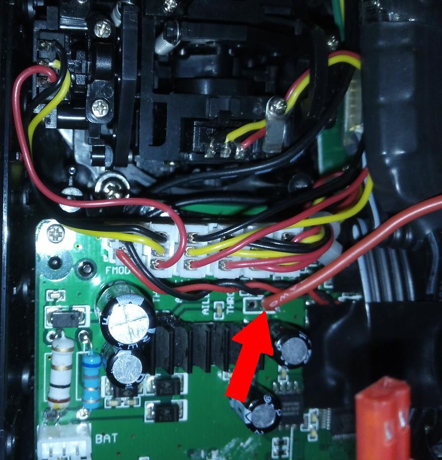
The pad to the left is full battery voltage, so be careful!

The pad to the left is full battery voltage, so be careful!
- Deal57
-
- Offline
Less
More
- Posts: 857
05 Aug 2015 01:48 #36566
by Deal57
Deviation Devo7e 3way switch mod, A7105, NRF24L01
Devo6s 2x2 switch mod, trim mod, haptic, multimodule, A7105, NRF24L01, CC2500
Devo12e 4-in-1 with voice mod -- it speaks!!
Replied by Deal57 on topic Extra inputs for Devo Tx's
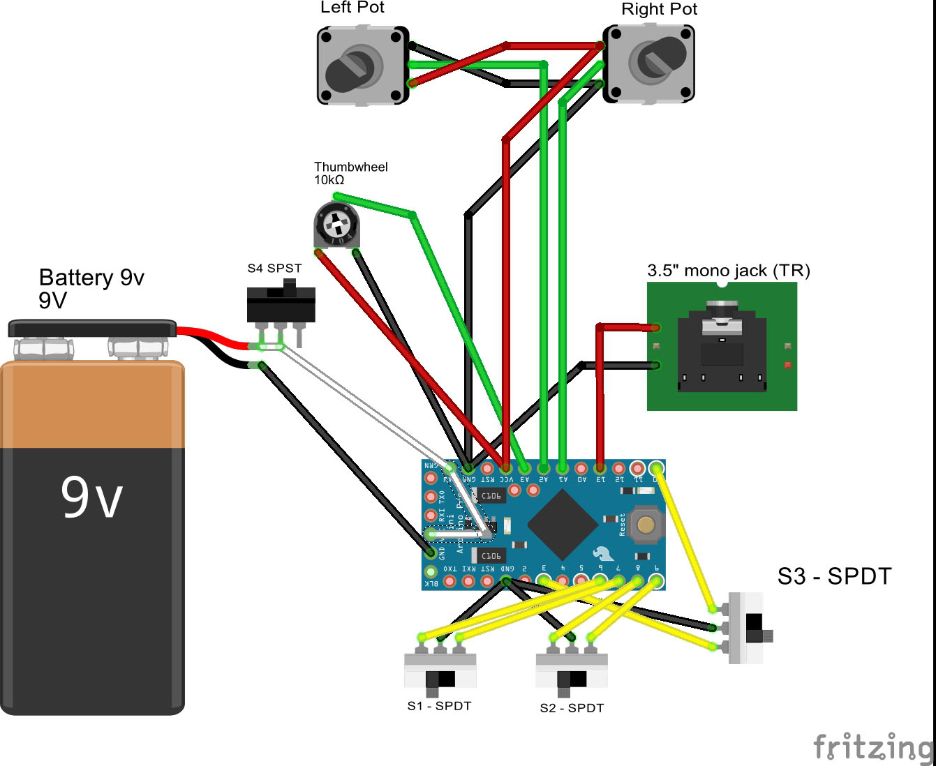
I got the parts sort of hooked together... I've had limited time to test everything, so it is not yet installed in my Devo7e. Here is the basic layout I am working with. The next step is to wire in the connector to the Devo7e power and to the DSC port. I have all the parts but not the time, yet!
- The code is written to allow three analog pots and 5 digital on/off switches.
- The red and black wires go to regulated voltage on the Devo7e. There are a few points to get this from. Looking at this I think we can install an on-off switch to shut off this mod if the user isn't using it.
- The D13, D12, D11, and D10 connections match up to the connections on the Devo7e DSC port. I probably should show that pin 4 (pin 10 on our Arduino) is connected to ground, and I'm thinking of just bringing it straight to ground. We only use the signal pin (pin 1/pin 13) for PPM out, and the RingShunt pin (pin 3/pin 11) because when it goes low we know that a plug is inserted in the jack. If pin 11 (ring shunt) is grounded the PPM output is left at high. Will this interrupt the signal coming out of the PPM In jack?
- I'm showing two 3-way switches rather than 4 two-way switches, but you can do it whatever way you like.
- We need to figure out why analog pots that are NOT connected show values that move when the connected ones move. We can of course comment out the programming lines but it seems there might be a better way..
- We CAN power this from the Devo7e, it will take anywhere from about 80mah to 150mah. If we need to program it, I think we just have to connect TX/RX/DTR and GND, but the Devo7e would have to be on unless we figure something else out.
// PPM Encoder Analog Add-ons for Devo7e
// For use with Arduino Pro Mini 328P
// J. Diehl 04/08/2015
// Based on a sketch by Ian Johnston 29/04/2010
//  modified by Epyon and Cereal_Killer
// Version 2.0
// Low cost way to add extra POT's to any radio that accepts PPM input for <$15
//  using an arduino nano and a few POT's, visit DeviationTX.com for info.
// POT's on A1 and A2, optional Thumbwheel on A3, optional switches on D6-D10
// PPM output on D13
//  PPM inout to tip of 3.5 stereo, this is the black wire on your Devo 7E
//  Ring Shunt on D11 when shorted indicate DSC port in use (e.g. Plug inserted)
//  this will stop monitoring the inputs and outputs until these are no longer shorted
//
//  Original Sketch uses:
//  A1-3 Analog in for Pots 1, 2 and 3
//  D6-10 Digital in for up to 5 switches
//  D11 - Devo7e DSC Port "Ring Shunt"  high; goes low when plug is inserted into DSC
//  D13 - PPM Output with LED


int potPin_A1= A1;  //Declare potPin_A1 to be analog pin A1
int potPin_A2= A2;  //Declare potPin_A2 to be analog pin A2
int potPin_A3= A3;  //Declare potPin_A3 to be analog pin A3
int AI_Raw_A1;        // Analog In raw var - 0->1023
int AI_Raw_A2;        // Analog In raw var - 0->1023
int AI_Raw_A3;        // Analog In raw var - 0->1023
int A1_uS = 750;     // Analog 1 uS var
int A2_uS = 750;     // Analog 2 uS var
int A3_uS = 750;     // Analog 3 uS var

int swPin_D1= 6;   //Declare swPin_D1 to be Digital pin 6
int swPin_D2= 7;   //Declare swPin_D2 to be Digital pin 7
int swPin_D3= 8;   //Declare swPin_D3 to be Digital pin 8
int swPin_D4= 9;   //Declare swPin_D4 to be Digital pin 9
int swPin_D5= 10;  //Declare swPin_D5 to be Digital pin 10
int sw1_uS = 750;     // Switch 1
int sw2_uS = 750;     // Switch 2
int sw3_uS = 750;     // Switch 3
int sw4_uS = 750;     // Switch 4 // not used
int sw5_uS = 750;     // Switch 5 // not used

int rshPin = 11; // DSC Ring Shunt ping goes to ground when DSC in use
int rshPinState;
 String rshPinStr; // debug

int outPinPPM = 13;  // Declare ppmPin to be arduino pin 13

int Fixed_uS = 300;       // PPM frame fixed LOW phase
int pulseMin = 750;          // pulse minimum width minus start in uS
int pulseMax = 1700;      // pulse maximum width in uS

ISR(TIMER1_COMPA_vect) {
    ppmoutput(); // Jump to ppmoutput subroutine
}


void setup() {
  pinMode(potPin_A1, INPUT);  //set potPin_A1 to be an input
  pinMode(potPin_A2, INPUT);  //set potPin_A2 to be an input
  pinMode(potPin_A3, INPUT);  //set potPin_A3 to be an input
  pinMode(swPin_D1, INPUT);  //set swPin_D1 to be an input
  digitalWrite(swPin_D1, HIGH);  // turn on pull-up resistor
  pinMode(swPin_D2, INPUT);  //set swPin_D2 to be an input
  digitalWrite(swPin_D2, HIGH);  // turn on pull-up resistor
  pinMode(swPin_D3, INPUT);  //set swPin_D3 to be an input
  digitalWrite(swPin_D3, HIGH);  // turn on pull-up resistor

//  pinMode(rngPin, INPUT);  //set rngPin to be an input - not used
  pinMode(rshPin, INPUT);  //set rshPin to be an input - do not initialize here
//  digitalWrite(rshPin, HIGH);
  pinMode(outPinPPM, OUTPUT); //set ppmPin to be an OUTPUT
  digitalWrite(outPinPPM, HIGH); // turn on LED

//  rshPinStr = "RSH: "; // debug string

     // Setup timer
  TCCR1A = B00110001; // Compare register B used in mode '3'
  TCCR1B = B00010010; // WGM13 and CS11 set to 1
  TCCR1C = B00000000; // All set to 0
  TIMSK1 = B00000010; // Interrupt on compare B
  TIFR1  = B00000010; // Interrupt on compare B
  OCR1A = 22000; // 22mS PPM output refresh
  OCR1B = 1000;


  Serial.begin(9600);      // turn on Serial Port

}

void ppmoutput() { // PPM output sub

if (rshPinState == HIGH) {

 // Channel 1 - Analog 1
  digitalWrite(outPinPPM, LOW);
  delayMicroseconds(Fixed_uS);    // Hold
  digitalWrite(outPinPPM, HIGH);
  delayMicroseconds(A1_uS);  // Hold for A1_uS microseconds

 // Channel 2 - Analog 2
  digitalWrite(outPinPPM, LOW);
  delayMicroseconds(Fixed_uS);    // Hold
  digitalWrite(outPinPPM, HIGH);
  delayMicroseconds(A2_uS);  // Hold for A2_uS microseconds

 // Channel 3 - Analog 3
  digitalWrite(outPinPPM, LOW);
  delayMicroseconds(Fixed_uS);    // Hold
  digitalWrite(outPinPPM, HIGH);
  delayMicroseconds(A3_uS);  // Hold for A3_uS microseconds

// Channel 4 - Switch 1
  digitalWrite(outPinPPM, LOW);
  delayMicroseconds(Fixed_uS);    // Hold
  digitalWrite(outPinPPM, HIGH);
  delayMicroseconds(sw1_uS);     // Hold for sw1_uS microseconds

// Channel 5 - Switch 2
  digitalWrite(outPinPPM, LOW);
  delayMicroseconds(Fixed_uS);    // Hold
  digitalWrite(outPinPPM, HIGH);
  delayMicroseconds(sw2_uS);     // Hold for sw2_uS microseconds

// Channel 6 - Switch 3
  digitalWrite(outPinPPM, LOW);
  delayMicroseconds(Fixed_uS);    // Hold
  digitalWrite(outPinPPM, HIGH);
  delayMicroseconds(sw3_uS);     // Hold for sw3_uS microseconds

// Channel 7 - Switch 4
  digitalWrite(outPinPPM, LOW);
  delayMicroseconds(Fixed_uS);    // Hold
  digitalWrite(outPinPPM, HIGH);
  delayMicroseconds(sw4_uS);     // Hold for sw4_uS microseconds

// Channel 8 - Switch 5
  digitalWrite(outPinPPM, LOW);
  delayMicroseconds(Fixed_uS);    // Hold
  digitalWrite(outPinPPM, HIGH);
  delayMicroseconds(sw5_uS);     // Hold for sw5_uS microseconds

 // Synchro pulse
  digitalWrite(outPinPPM, LOW);
  delayMicroseconds(Fixed_uS);    // Hold
  digitalWrite(outPinPPM, HIGH);  // Start Synchro pulse

//  Serial.println(rshPinStr + rshPinState);
/* Serial.print("You are writing a value of ");  //for debugging print your values
 Serial.print(A1_uS);
 Serial.print("  ");
 Serial.print(A2_uS);
 Serial.print("  ");
 Serial.print(A3_uS);
 Serial.print("  ");
 Serial.print(sw1_uS);
 Serial.print("  ");
 Serial.print(sw2_uS);
 Serial.print("  ");
 Serial.print(sw3_uS);
 Serial.print("  ");
 Serial.print(sw4_uS);
 Serial.print("  ");
 Serial.print(sw5_uS);
 Serial.print("  ");

 Serial.println(" End");
*/
}
 else {
//  Serial.println(rshPinStr + rshPinState);
 }
}


void loop() {

// logic used to determine if the DSC port has a plug inserted
//   set pin 11 to HIGH until it is LOW
//   this will indicate that there is a plug in the DSC jack
//

//  digitalWrite(rshPin, HIGH);
  rshPinState = digitalRead(rshPin);

// logic to read each analog input

 // Read analog pins
   AI_Raw_A1 = analogRead(potPin_A1); // Analog Pot 1
   AI_Raw_A2 = analogRead(potPin_A2); // Analog Pot 2
   AI_Raw_A3 = analogRead(potPin_A3); // Thumbwheel Pot 3

 // Map analog inputs to PPM rates for each of the channels
   A1_uS = AI_Raw_A1 + pulseMin;
   A2_uS = AI_Raw_A2 + pulseMin;
   A3_uS = AI_Raw_A3 + pulseMin;

 // Check limits
  if (A1_uS <= 750) A1_uS = 750;     // Min
  if (A1_uS >= 1700) A1_uS = 1700;   // Max
  if (A2_uS <= 750) A2_uS = 750;   // Min
  if (A2_uS >= 1700) A2_uS = 1700; // Max
  if (A3_uS <= 750) A3_uS = 750;   // Min
  if (A3_uS >= 1700) A3_uS = 1700; // Max

  if (digitalRead(swPin_D1) == 1) { // Switch 1
           sw1_uS = 1700;
 } else {
           sw1_uS = 750;
 }
  if (digitalRead(swPin_D2) == 1) { // Switch 2
           sw2_uS = 1700;
 } else {
           sw2_uS = 750;
 }
  if (digitalRead(swPin_D3) == 1) { // Switch 3
           sw3_uS = 1700;
 } else {
           sw3_uS = 750;
 }
  if (digitalRead(swPin_D4) == 1) { // Switch 4
           sw4_uS = 1700;
 } else {
           sw4_uS = 750;
 }
  if (digitalRead(swPin_D5) == 1) { // Switch 5
           sw5_uS = 1700;
 } else {
           sw5_uS = 750;
 }
}
Deviation Devo7e 3way switch mod, A7105, NRF24L01
Devo6s 2x2 switch mod, trim mod, haptic, multimodule, A7105, NRF24L01, CC2500
Devo12e 4-in-1 with voice mod -- it speaks!!
- Arakon
-
- Offline
Less
More
- Posts: 305
05 Aug 2015 07:47 #36574
by Arakon
Replied by Arakon on topic Extra inputs for Devo Tx's
5) Explains the issue I had before then, where the single pot I had hooked up moved all of the channels.
- robocog
-
- Offline
05 Aug 2015 20:12 #36592
by robocog
Replied by robocog on topic Extra inputs for Devo Tx's
USB uart arrived today, as did the pots
No Arduinos yet though (hoping tomorrow)
I am still a little confused over what physical connections I need to connect the 'usb uart' to the Arduino to get the info across successfully
(do I need extra capacitors and resistors? - something for the reset line? is the Arduino powered solely by the usb uart till it has been programmed? or do I need to hook up 5v and ground to the board first?
Will there be a popup box telling me it has been programmed successfully? ....or if it has failed?
Have seen a few vids but I am still a little confused - no-one seemed to adjust the "Tools>Programmer" type
Sketch is set to "USBTinyISP" for its programmer type is that right?
Hoping it will all become obvious/just work once the parts arrive and hooked up together
Some videos seemed to show resistors and capacitors hooked up as well...and didn't explain what they were for
Sorry for all the newbie questions, but I am a complete newbie and a bit lost
Regards
Rob
- mwm
-
Topic Author
- Offline
05 Aug 2015 21:25 #36594
by mwm
Sorry if you posted this before, or bought what someone provided a link to, but what exactly do you mean by "usb uart"?
Typically, you need an USB/FTDI connector. It plugs into the USB cable, and has pins (or holes that you'll need to fit pins through) that connect directly to matching holes on the arduino. It provides power to the arduino, and you just have to keep it connected while you press the "download' button on the IDE. While you can plug it in backwards, it's harmless to do so. Unless maybe you bought a 5V programmer and a 3.3V arduino, in which case it won't do any more damage plugged in backwards than it will plugged in forwards.
Do not ask me questions via PM. Ask in the forums, where I'll answer if I can.
My remotely piloted vehicle ("drone") is a yacht.
Replied by mwm on topic Extra inputs for Devo Tx's
robocog wrote: I am still a little confused over what physical connections I need to connect the 'usb uart' to the Arduino to get the info across successfully
Sorry if you posted this before, or bought what someone provided a link to, but what exactly do you mean by "usb uart"?
Typically, you need an USB/FTDI connector. It plugs into the USB cable, and has pins (or holes that you'll need to fit pins through) that connect directly to matching holes on the arduino. It provides power to the arduino, and you just have to keep it connected while you press the "download' button on the IDE. While you can plug it in backwards, it's harmless to do so. Unless maybe you bought a 5V programmer and a 3.3V arduino, in which case it won't do any more damage plugged in backwards than it will plugged in forwards.
Do not ask me questions via PM. Ask in the forums, where I'll answer if I can.
My remotely piloted vehicle ("drone") is a yacht.
- robocog
-
- Offline
05 Aug 2015 22:17 #36596
by robocog
Replied by robocog on topic Extra inputs for Devo Tx's
It's the CP2102 board I got (USB to a set of pins)
( I thought it was a UART?)
Connections on the edge with pins
DTR
RXD
TXD
+5v
GND
3V3
The bits I do understand
I have bought 5v Arduino's so obviously its 5v to 5v there (ignoring the 3V3 pin on the CP2102)
gnd - gnd,
TX - RX
RX - TX
DTR - DTR
In the Sketch program I can set the com port of the CP2102 when its plugged in
I have selected the right Arduino variant in the Processor type
At this point I am out of my depth - and as far as I can go till the Arduino's land
Is this simply enough to get the task done?
Do I need to set a programmer type in Sketch?
Is it really as simple as hook it all up as above load the text file into sketch , click compile and then upload it ?
Assuming this goes to plan...
Un hook the Arduino from the CP2102, solder up the pots and power and output and enjoy the twiddly knobs? (after minor TX config to utilise them)
I have seen images like this
store.picbg.net/pubpic/C1/05/4d3efbf3a5c2c105.png
Do I need the extra components?
The CP2102 also has extra through holes without pins VCD DSR RTS CTS RST RI SUS and SUS (not with a line above)
I have just (out of sheer curiosity) plugged the CP2102 in and done a 'dummy run' without the Arduino (because they are not here yet!) and see it does eventually give an uploading error - when I tried before it just seemed to sit there and wasn't sure if it DOES give any indication it has tried and failed and started to worry - I hadn't waited long enough for it to time out I guess LOL
(it at least answers a few doubts I had)
Regards
Rob
- Deal57
-
- Offline
Less
More
- Posts: 857
06 Aug 2015 00:20 #36598
by Deal57
Deviation Devo7e 3way switch mod, A7105, NRF24L01
Devo6s 2x2 switch mod, trim mod, haptic, multimodule, A7105, NRF24L01, CC2500
Devo12e 4-in-1 with voice mod -- it speaks!!
Replied by Deal57 on topic Extra inputs for Devo Tx's
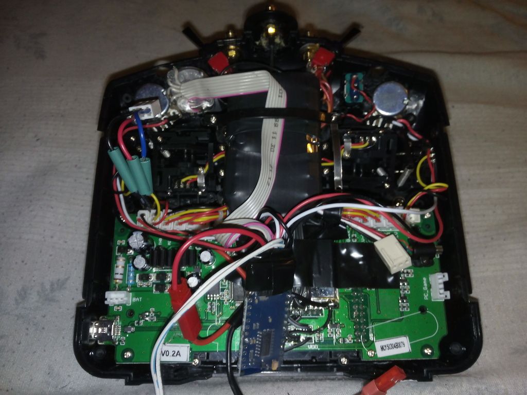
I hope this will be helpful, this is what I did. I'm not an Arduino expert, but I know enough software and hardware to get around (35+ years in the IT biz). It's taken me about a week to get through all the parts and pieces to the point that I'm ready to plug it into the Devo7e... and it worked!
Starting out, just get used to the Arduino. To program the Arduino, you'll need to connect Vcc, Gnd, TXD, RXD and DTR from the USB FTDI board (the red board in my photo) to the Arduino. In my first photo you can see the two devices connected -- sorry for all the extra wiring but I'm still testing a few things! If you want to get some programming experience, I suggest that you just play with the Arduino a bit. You can download the Arduino programming tools and once they're installed, you configure the comm port for the USB FTDI connection. I loaded some of the examples, things like blink - an example of how to blink the on-board LED, etc. You can also just copy/paste my code but until everything else is connected there isn't much to see. I suggest you use the Serial Monitor option for the examples, because they're set up to send info to the serial port. You can also uncomment my debug "serial.print()" statements (remove the "//" from the line) and it will send info, but since the serial port runs at 9600 baud, the buffer fills up and it takes a while to see the effect of changing controls.
copy.jpg)
My next exercise was laying out the pots and switches, getting them wired in. I'm still not comfortable some of the power wiring and I'm still playing with the cabling to the DSC port (the Devo PPM in). But it does work as you can see. I set mine up with two pots and a thumbwheel. This sort of gives me the pots and sliders I'm looking for. I also wired in two 3-way switches set up as four on-off switches... I am thinking I want to work with the software to mux them into giving me effective 3-way switching, but that's later. You could use up to five 2-way switches in my sketch.
The drawings in my prior post are accurate so far (as far as connections), and while it's not really done,I hope that it's close enough for you to use. If you need help with the Arduino code or any of this mess, PM me or post here.
Starting out, just get used to the Arduino. To program the Arduino, you'll need to connect Vcc, Gnd, TXD, RXD and DTR from the USB FTDI board (the red board in my photo) to the Arduino. In my first photo you can see the two devices connected -- sorry for all the extra wiring but I'm still testing a few things! If you want to get some programming experience, I suggest that you just play with the Arduino a bit. You can download the Arduino programming tools and once they're installed, you configure the comm port for the USB FTDI connection. I loaded some of the examples, things like blink - an example of how to blink the on-board LED, etc. You can also just copy/paste my code but until everything else is connected there isn't much to see. I suggest you use the Serial Monitor option for the examples, because they're set up to send info to the serial port. You can also uncomment my debug "serial.print()" statements (remove the "//" from the line) and it will send info, but since the serial port runs at 9600 baud, the buffer fills up and it takes a while to see the effect of changing controls.
My next exercise was laying out the pots and switches, getting them wired in. I'm still not comfortable some of the power wiring and I'm still playing with the cabling to the DSC port (the Devo PPM in). But it does work as you can see. I set mine up with two pots and a thumbwheel. This sort of gives me the pots and sliders I'm looking for. I also wired in two 3-way switches set up as four on-off switches... I am thinking I want to work with the software to mux them into giving me effective 3-way switching, but that's later. You could use up to five 2-way switches in my sketch.
The drawings in my prior post are accurate so far (as far as connections), and while it's not really done,I hope that it's close enough for you to use. If you need help with the Arduino code or any of this mess, PM me or post here.
Deviation Devo7e 3way switch mod, A7105, NRF24L01
Devo6s 2x2 switch mod, trim mod, haptic, multimodule, A7105, NRF24L01, CC2500
Devo12e 4-in-1 with voice mod -- it speaks!!
- Fernandez
-
- Offline
Less
More
- Posts: 983
06 Aug 2015 13:31 - 06 Aug 2015 13:32 #36605
by Fernandez
Replied by Fernandez on topic Extra inputs for Devo Tx's
I normally use this one, for 30ct extra, it comes with the USB, makes life easy.
www.banggood.com/ATmega328P-Nano-V3-Cont...rduino-p-940937.html
www.banggood.com/ATmega328P-Nano-V3-Cont...rduino-p-940937.html
Last edit: 06 Aug 2015 13:32 by Fernandez.
- mwm
-
- Offline
06 Aug 2015 14:33 #36608
by mwm
Do not ask me questions via PM. Ask in the forums, where I'll answer if I can.
My remotely piloted vehicle ("drone") is a yacht.
Replied by mwm on topic Extra inputs for Devo Tx's
It really is a UART, not an FTDI driver. It's a bit more complicated than the FTDI stuff I buy, but less expensive. The FTDI means I can buy the non-USB arduinos and use them with no more problem than the USB ones.
I found this: .
I found this: .
Do not ask me questions via PM. Ask in the forums, where I'll answer if I can.
My remotely piloted vehicle ("drone") is a yacht.
- Deal57
-
- Offline
Less
More
- Posts: 857
08 Aug 2015 21:17 - 08 Aug 2015 21:24 #36690
by Deal57
Deviation Devo7e 3way switch mod, A7105, NRF24L01
Devo6s 2x2 switch mod, trim mod, haptic, multimodule, A7105, NRF24L01, CC2500
Devo12e 4-in-1 with voice mod -- it speaks!!
Replied by Deal57 on topic Extra inputs for Devo Tx's
I had hoped to post my finished results, but overlooked one big issue: the Devo7e has VERY limited space inside! My potentiometers are simply too big to fit where I need them. So I'm putting this assembly into an enclosure box with a battery, which will use a mono audio cable to plug into the Devo 7e DSC port. Note that 9V power must come into the RAW input. I'll post my notes when I have it done.
I did get the 3-way switch functionality working, but the switch values are not calibrated. I can probably fix that in the Ini file but I'd prefer to get it right in the Arduino if I can. If you want a copy of my working software sketch, please PM me; I don't think I should post this until I figure out how to properly calibrate these inputs.
I did get the 3-way switch functionality working, but the switch values are not calibrated. I can probably fix that in the Ini file but I'd prefer to get it right in the Arduino if I can. If you want a copy of my working software sketch, please PM me; I don't think I should post this until I figure out how to properly calibrate these inputs.
Deviation Devo7e 3way switch mod, A7105, NRF24L01
Devo6s 2x2 switch mod, trim mod, haptic, multimodule, A7105, NRF24L01, CC2500
Devo12e 4-in-1 with voice mod -- it speaks!!
Last edit: 08 Aug 2015 21:24 by Deal57. Reason: Added 9V info and updated drawing
- aMax
-
- Offline
Less
More
- Posts: 776
09 Aug 2015 00:27 #36693
by aMax
Devo7e, TaranisQ X7, R9M , 4in1 MM, Futaba FC18plusV3.2 & DFT/FLD-02
Replied by aMax on topic Extra inputs for Devo Tx's
Anyways, I really like this external solution. Space is rare on the 7e and who knows what mod comes next.
Devo7e, TaranisQ X7, R9M , 4in1 MM, Futaba FC18plusV3.2 & DFT/FLD-02
- Epyon
-
- Offline
Less
More
- Posts: 57
11 Aug 2015 20:24 - 15 Aug 2015 21:09 #36805
by Epyon
Replied by Epyon on topic Extra inputs for Devo Tx's
Got everything, and then some crammed into my 7e............
I've got three 3-way switches, one 2-way switch, one 6-way rotary switch, two momentary switches, four momentary buttons, and two pots!!
The pots, rotary switch and one of the 3-ways are run through an Arduino Nano. Here's my current sketch..........................
I've changed the 6-way switch to output as an analog channel in the PPM stream instead of 6 separate channels. I still gotta figure out how to configure virtual channels on the Devo to allow toggle icons for flight modes.
Also added a piezo buzzer, throttle hold alarm, and pot center beeps. However I need to figure out how to make the beeps only repeat once if pot left centered.


I've got three 3-way switches, one 2-way switch, one 6-way rotary switch, two momentary switches, four momentary buttons, and two pots!!
The pots, rotary switch and one of the 3-ways are run through an Arduino Nano. Here's my current sketch..........................
// Devo 7e PPM input
// For use with Arduino Nano V3.0
// Based on sketch by Ian Johnston

int AI_Pin_A1 = 1;    // Analog In 1
int AI_Pin_A2 = 2;    // Analog In 2
int AI_Raw_A1;        // Analog In raw var - 0->1023
int AI_Raw_A2;        // Analog In raw var - 0->1023
int A1_uS = 750;     // Analog 1 uS var
int A2_uS = 750;     // Analog 2 uS var
int sw1_uS = 750;     // 6-way switch
int sw2_uS = 750;     // 3-way switch pos 0
int sw3_uS = 750;     // 3-way switch pos 1
int sw4_uS = 750;     // 3-way switch pos 2

int Fixed_uS = 300;       // PPM frame fixed LOW phase
int pulseMin = 750;       // pulse minimum width minus start in uS
int pulseMax = 1700;      // pulse maximum width in uS

int outPinPPM = 10;       // PPM out on digital pin 10
int inPinD1 = 2;        // 6-way inputs: digital pin 2
int inPinD2 = 3;        // digital pin 3
int inPinD3 = 4;        // digital pin 4
int inPinD4 = 5;        // digital pin 5
int inPinD5 = 6;        // digital pin 6
int inPinD6 = 7;        // digital pin 7
int inPinD7 = 8;        // 3-way inputs: digital pin 8
int inPinD8 = 9;        // digital pin 9

int piezoPin = 13;        // piezo buzzer on digital pin 13

boolean Beep1 = false;
boolean Beep2 = false;
boolean Beep3 = false;
boolean Beep4 = false;
boolean Beep5 = false;
boolean Beep6 = false;

ISR(TIMER1_COMPA_vect) {
    ppmoutput(); // Jump to ppmoutput subroutine
}

void setup() {

  // Serial.begin(9600) ; // Test

  pinMode(outPinPPM, OUTPUT);   // sets the digital pin as output
  pinMode(inPinD1, INPUT);      // sets the digital pin as input
  digitalWrite(inPinD1, HIGH);  // turn on pull-up resistor
  pinMode(inPinD2, INPUT);
  digitalWrite(inPinD2, HIGH);
  pinMode(inPinD3, INPUT);
  digitalWrite(inPinD3, HIGH);
  pinMode(inPinD4, INPUT);
  digitalWrite(inPinD4, HIGH);
  pinMode(inPinD5, INPUT);
  digitalWrite(inPinD5, HIGH);
  pinMode(inPinD6, INPUT);
  digitalWrite(inPinD6, HIGH);
  pinMode(inPinD7, INPUT);
  digitalWrite(inPinD7, HIGH);
  pinMode(inPinD8, INPUT);
  digitalWrite(inPinD8, HIGH);

   // Setup timer
  TCCR1A = B00110001; // Compare register B used in mode '3'
  TCCR1B = B00010010; // WGM13 and CS11 set to 1
  TCCR1C = B00000000; // All set to 0
  TIMSK1 = B00000010; // Interrupt on compare B
  TIFR1  = B00000010; // Interrupt on compare B
  OCR1A = 22000; // 22mS PPM output refresh
  OCR1B = 1000;

}


void ppmoutput() { // PPM output sub

 // Channel 1 - Analog 1
  digitalWrite(outPinPPM, LOW);
  delayMicroseconds(Fixed_uS);    // Hold
  digitalWrite(outPinPPM, HIGH);
  delayMicroseconds(A1_uS);  // Hold for A1_uS microseconds

 // Channel 2 - Analog 2
  digitalWrite(outPinPPM, LOW);
  delayMicroseconds(Fixed_uS);    // Hold
  digitalWrite(outPinPPM, HIGH);
  delayMicroseconds(A2_uS); // Hold for A2_uS microseconds

// Channel 3 - 6-way switch
  digitalWrite(outPinPPM, LOW);
  delayMicroseconds(Fixed_uS);    // Hold
  digitalWrite(outPinPPM, HIGH);
  delayMicroseconds(sw1_uS);     // Hold for sw1_uS microseconds

// Channel 4 - 3-way switch pos 0
  digitalWrite(outPinPPM, LOW);
  delayMicroseconds(Fixed_uS);    // Hold
  digitalWrite(outPinPPM, HIGH);
  delayMicroseconds(sw2_uS);     // Hold for sw2_uS microseconds

// Channel 5 - 3-way switch pos 1
  digitalWrite(outPinPPM, LOW);
  delayMicroseconds(Fixed_uS);    // Hold
  digitalWrite(outPinPPM, HIGH);
  delayMicroseconds(sw3_uS);     // Hold for sw3_uS microseconds

// Channel 6 - 3-way switch pos 2
  digitalWrite(outPinPPM, LOW);
  delayMicroseconds(Fixed_uS);    // Hold
  digitalWrite(outPinPPM, HIGH);
  delayMicroseconds(sw4_uS);     // Hold for sw4_uS microseconds

// Synchro pulse
  digitalWrite(outPinPPM, LOW);
  delayMicroseconds(Fixed_uS);    // Hold
  digitalWrite(outPinPPM, HIGH);  // Start Synchro pulse

}


void loop() { // Main loop

 // Read analog pins
   AI_Raw_A1 = analogRead(AI_Pin_A1);
   AI_Raw_A2 = analogRead(AI_Pin_A2);

 // Map analog inputs to PPM rates for each of the channels
   A1_uS = AI_Raw_A1 + pulseMin;
   A2_uS = AI_Raw_A2 + pulseMin;

 // Check limits
  if (A1_uS <= 750) A1_uS = 750;     // Min
  if (A1_uS >= 1700) A1_uS = 1700;   // Max
  if (A2_uS <= 750) A2_uS = 750;   // Min
  if (A2_uS >= 1700) A2_uS = 1700; // Max

  if (digitalRead(inPinD1) == 0) { // Switch 1
           sw1_uS = 750;
      if (Beep1 == false)
       tone(piezoPin, 2850, 50);
       delay(50);
       Beep1 = true;
 } else {
        noTone(piezoPin);
        Beep1 = false;
 }
  if (digitalRead(inPinD2) == 0) { // Switch 2
           sw1_uS = 910;
      if (Beep2 == false)
       tone(piezoPin, 2850, 50);
       delay(50);
       Beep2 = true;
 } else {
        noTone(piezoPin);
        Beep2 = false;
 }
  if (digitalRead(inPinD3) == 0) { // Switch 3
           sw1_uS = 1120;
           if (Beep3 == false)
       tone(piezoPin, 2850, 50);
       delay(50);
       Beep3 = true;
 } else {
        noTone(piezoPin);
        Beep3 = false;
 }
  if (digitalRead(inPinD4) == 0) { // Switch 4
           sw1_uS = 1330;
           if (Beep4 == false)
       tone(piezoPin, 2850, 50);
       delay(50);
       Beep4 = true;
 } else {
        noTone(piezoPin);
        Beep4 = false;
 }
  if (digitalRead(inPinD5) == 0) { // Switch 5
           sw1_uS = 1540;
           if (Beep5 == false)
       tone(piezoPin, 2850, 50);
       delay(50);
       Beep5 = true;
 } else {
        noTone(piezoPin);
        Beep5 = false;
 }
  if (digitalRead(inPinD6) == 0) { // Switch 6
           sw1_uS = 1700;
           tone(piezoPin, 2850, 100);
           delay(100);
           tone(piezoPin, 2700, 100);
           delay(100);
           tone(piezoPin, 2600, 100);
           delay(100);
 }
  if (digitalRead(inPinD7) == 0) { // Switch 7
           sw2_uS = 750;
 } else {
           sw2_uS = 1700;
 }
  if ((digitalRead(inPinD7) == 1) && (digitalRead(inPinD8) == 1)) { // Switch 8
           sw3_uS = 750;
 } else {
           sw3_uS = 1700;
 }
  if (digitalRead(inPinD8) == 0) { // Switch 9
           sw4_uS = 750;
 } else {
           sw4_uS = 1700;
 }
}
I've changed the 6-way switch to output as an analog channel in the PPM stream instead of 6 separate channels. I still gotta figure out how to configure virtual channels on the Devo to allow toggle icons for flight modes.
Also added a piezo buzzer, throttle hold alarm, and pot center beeps. However I need to figure out how to make the beeps only repeat once if pot left centered.
Last edit: 15 Aug 2015 21:09 by Epyon. Reason: Updated sketch
- mwm
-
- Offline
12 Aug 2015 06:34 #36817
by mwm
Do not ask me questions via PM. Ask in the forums, where I'll answer if I can.
My remotely piloted vehicle ("drone") is a yacht.
Replied by mwm on topic Extra inputs for Devo Tx's
Toggle icons for flight modes doesn't work very well. You can't get more than three icons in one position, and that only works for three way switches. I actually created a pull request that allowed many icons in one position, but it didn't fit on the 7e. Possibly PBs latest size reduction will resurrect it. But even then, we really need someone with artistic skills (meaning not me) to create a set of icons for modern flight modes.
Personally, I think toggle icons are, um, dated. I'd rather have voice alerts than updated icons.
Personally, I think toggle icons are, um, dated. I'd rather have voice alerts than updated icons.
Do not ask me questions via PM. Ask in the forums, where I'll answer if I can.
My remotely piloted vehicle ("drone") is a yacht.
- Epyon
-
- Offline
Less
More
- Posts: 57
12 Aug 2015 09:27 - 12 Aug 2015 09:28 #36821
by Epyon
A sound mod would be awesome. I'm gonna rig up a crude one with an I2C .wav board, but it'll just work off switch positions connected to the Arduino so different models would need code changed. Or another................switch added to trigger which sound set is played. I've been playing around with piezo tones for switch positions. The buzzer I used has very limited frequency range so haven't gotten much in the way of distinct sounds.
I would still require a visual indicator of flight mode so I'll be adding a small OLED display. Again, this will need additional input to work between models.
As far as Deviation, the proposed ASCII display for toggles seems like a great solution.
I did get one of my model.ini's working with toggles, 19 of them to be exact!! Also 6 virtual channels to trigger them.
Replied by Epyon on topic Extra inputs for Devo Tx's
mwm wrote: Personally, I think toggle icons are, um, dated. I'd rather have voice alerts than updated icons.
A sound mod would be awesome. I'm gonna rig up a crude one with an I2C .wav board, but it'll just work off switch positions connected to the Arduino so different models would need code changed. Or another................switch added to trigger which sound set is played. I've been playing around with piezo tones for switch positions. The buzzer I used has very limited frequency range so haven't gotten much in the way of distinct sounds.
I would still require a visual indicator of flight mode so I'll be adding a small OLED display. Again, this will need additional input to work between models.
As far as Deviation, the proposed ASCII display for toggles seems like a great solution.
I did get one of my model.ini's working with toggles, 19 of them to be exact!! Also 6 virtual channels to trigger them.
Last edit: 12 Aug 2015 09:28 by Epyon.
- FDR
-
- Offline
12 Aug 2015 11:13 - 12 Aug 2015 11:14 #36824
by FDR
Replied by FDR on topic Extra inputs for Devo Tx's
What signal does the current piezo get?
If we removed the piezo, and detected the frequency of the piezo signal with an added module, we could play different voice alerts based on the detected frequency...
If we removed the piezo, and detected the frequency of the piezo signal with an added module, we could play different voice alerts based on the detected frequency...
Last edit: 12 Aug 2015 11:14 by FDR.
- Epyon
-
- Offline
Less
More
- Posts: 57
13 Aug 2015 00:09 #36832
by Epyon
Replied by Epyon on topic Extra inputs for Devo Tx's
I'm pretty sure it's just square wave PWM. It should be easy enough to read with Arduino. I'm waiting on a sound board to arrive off the slow boat, I may dig into this. I've already been downloading a bunch of sounds for Taranis's.
My 7e needs a sexy voice!
My 7e needs a sexy voice!
Time to create page: 0.292 seconds
-
Home

-
Forum
-
Development
-
Development
- Extra inputs for Devo Tx's