
- Posts: 65
Ultimate7e tutorial: Processor upgrade
- compman2
-
- Offline
Less
More
04 May 2017 13:43 - 04 May 2017 13:43 #61988
by compman2
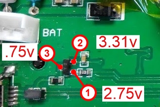
So I checked my voltages with in program mode and I didn't get 3v3 on pin 3. I have encluded a photo with the voltages I got by pin. After looking at this does that mean that the transistor is bad? Can I run a jumper from pin 2 to pin 3 to get the 3v3 on pin 3?
computer nerd, hobby collector, proud father
Replied by compman2 on topic Ultimate7e tutorial: Processor upgrade
silpstream wrote: I actually meant pin 3 on the transistor as shown in the picture I posted above. You should get 3v3 there. NOT the mcu. Sorry if I wasn't clear.
So I checked my voltages with in program mode and I didn't get 3v3 on pin 3. I have encluded a photo with the voltages I got by pin. After looking at this does that mean that the transistor is bad? Can I run a jumper from pin 2 to pin 3 to get the 3v3 on pin 3?
computer nerd, hobby collector, proud father
Last edit: 04 May 2017 13:43 by compman2.
- silpstream
-
Topic Author
- Offline
Less
More
- Posts: 244
04 May 2017 14:43 #61992
by silpstream
Replied by silpstream on topic Ultimate7e tutorial: Processor upgrade
If you are only getting 0.7v then something is definitely wrong. try running the jumper between Pin 2 to Pin 3. This should just be temporary though, so change the transistor when you get a chance. It's a SS8550 in a SOT23 package. Easy to find.
- Sko
-
- Offline
Less
More
- Posts: 2
04 May 2017 19:01 #62005
by Sko
Replied by Sko on topic Ultimate7e tutorial: Processor upgrade
I`ve managed to beat the problems. Turned out I've just fail to solder it properly from the first attempt. So I've use solder paste and then have to use wick to remove three shortages between legs.Visually all was ok, but with multimeter I found 3 shortages between neighboring legs.
- compman2
-
- Offline
Less
More
- Posts: 65
05 May 2017 01:34 - 05 May 2017 06:14 #62011
by compman2
Thanks for you help. The jumper did indeed get the usb problem fixed. I was able to load deviation and the file subsystem. I am ordering a replacement transistor. Any idea how it fried? Could it have been shorted pins on the MCU?
It was such a mystery to me why it wasn't working because the solder joints on the mcu look so good. All is well now. I was about to do another mcu swap which wouldn't have fixed the problem. Thanks so much for you help silpstream!
Another Ultimate 7e in the wild!
computer nerd, hobby collector, proud father
Replied by compman2 on topic Ultimate7e tutorial: Processor upgrade
silpstream wrote: If you are only getting 0.7v then something is definitely wrong. try running the jumper between Pin 2 to Pin 3. This should just be temporary though, so change the transistor when you get a chance. It's a SS8550 in a SOT23 package. Easy to find.
Thanks for you help. The jumper did indeed get the usb problem fixed. I was able to load deviation and the file subsystem. I am ordering a replacement transistor. Any idea how it fried? Could it have been shorted pins on the MCU?
It was such a mystery to me why it wasn't working because the solder joints on the mcu look so good. All is well now. I was about to do another mcu swap which wouldn't have fixed the problem. Thanks so much for you help silpstream!
Another Ultimate 7e in the wild!
computer nerd, hobby collector, proud father
Last edit: 05 May 2017 06:14 by compman2.
- silpstream
-
- Offline
Less
More
- Posts: 244
05 May 2017 06:36 #62019
by silpstream
Replied by silpstream on topic Ultimate7e tutorial: Processor upgrade
Good stuff! Glad both of you managed to sort it out.
@compman2, try checking for shorts next to the USB enable pin (PB10). It could be that your transistor is good, but one of the neighbouring pins (PB2 or PB11) is preventing USB enable from toggling low (i.e pulling the line up). Try checking using both the continuity as well as the ohmmeter setting on your multimeter.
@compman2, try checking for shorts next to the USB enable pin (PB10). It could be that your transistor is good, but one of the neighbouring pins (PB2 or PB11) is preventing USB enable from toggling low (i.e pulling the line up). Try checking using both the continuity as well as the ohmmeter setting on your multimeter.
- offspringfan
-
- Offline
Less
More
- Posts: 7
22 May 2017 13:15 - 22 May 2017 13:17 #62491
by offspringfan
Replied by offspringfan on topic Ultimate7e tutorial: Processor upgrade
I just upgraded the processor, flashed the bootloader and uploaded the latest nightly.
But i get an error on startup: "Missing Modules: CYRF6936"
I can't just click it away. When pressing the enter button, I start USB mode, on ext I get to DFU mode. I managed to get past there once, so im sure the Buttons are all working correctly.
Also I double checked the four connections to the CYRF6936 module. I used the complete stock filesystem, no extra switches or modules installed at the moment.
This is my errors.txt:
[Hard fault]
devo7e-256-v5.0.0-144bdd2
R0 = 00000000
R1 = 10000000
R2 = 00000000
R3 = 2000035c
R12 = 00000020
LR [R14] (subroutine call return address) = 0802d023
PC [R15] (program counter) = 0802d022
PSR = 01000000
BFAR = e000ed38
CFSR = 00000400
HFSR = 40000000
DFSR = 00000000
AFSR = 00000000
SCB_SHCSR = 00000000
Top of Stack:2000c000
Stack Detect:2000bf70
Backtrace:
2000bf84 : 0802d023
2000bf9c : 0802d14f
2000bfa0 : 0801ef71
2000bfa4 : 0801f083
2000bfc4 : 08028f03
2000bfcc : 080293a7
2000bfdc : 0800b4fb
2000bfec : 0800b5ef
2000bffc : 080330e9
Done
Any ideas?
But i get an error on startup: "Missing Modules: CYRF6936"
I can't just click it away. When pressing the enter button, I start USB mode, on ext I get to DFU mode. I managed to get past there once, so im sure the Buttons are all working correctly.
Also I double checked the four connections to the CYRF6936 module. I used the complete stock filesystem, no extra switches or modules installed at the moment.
This is my errors.txt:
Warning: Spoiler!
[ Click to expand ]
[ Click to hide ]
[Hard fault]
devo7e-256-v5.0.0-144bdd2
R0 = 00000000
R1 = 10000000
R2 = 00000000
R3 = 2000035c
R12 = 00000020
LR [R14] (subroutine call return address) = 0802d023
PC [R15] (program counter) = 0802d022
PSR = 01000000
BFAR = e000ed38
CFSR = 00000400
HFSR = 40000000
DFSR = 00000000
AFSR = 00000000
SCB_SHCSR = 00000000
Top of Stack:2000c000
Stack Detect:2000bf70
Backtrace:
2000bf84 : 0802d023
2000bf9c : 0802d14f
2000bfa0 : 0801ef71
2000bfa4 : 0801f083
2000bfc4 : 08028f03
2000bfcc : 080293a7
2000bfdc : 0800b4fb
2000bfec : 0800b5ef
2000bffc : 080330e9
Done
Any ideas?
Last edit: 22 May 2017 13:17 by offspringfan.
- Fernandez
-
- Offline
Less
More
- Posts: 983
22 May 2017 15:12 #62494
by Fernandez
Replied by Fernandez on topic Ultimate7e tutorial: Processor upgrade
What I can remember, I had one time strange stuff like that. (not particular related to the U7E new processor).
Please try to give a full re-format of the devo drive letter. Than copy all files and folders back fresh. Then nicely close the usb, using usb removal, not just unplug.
Please try to give a full re-format of the devo drive letter. Than copy all files and folders back fresh. Then nicely close the usb, using usb removal, not just unplug.
- offspringfan
-
- Offline
Less
More
- Posts: 7
22 May 2017 15:38 - 22 May 2017 16:02 #62495
by offspringfan
Replied by offspringfan on topic Ultimate7e tutorial: Processor upgrade
Tried that. No change. 
What I think is strange is that sometimes I get no USB and DFU screen when I start it holding the button down.
I get the USB screen when I press and hold ENT button after startup. I can't get to DFU that way.
I should mention that the missing module error just shows up when I press DN button. Splashscreen is missing, too. When not pressing any button, the display lights up some time and then goes out.
I use DevoDfuSe 2.0. Is it normal that there is no option for veryfying the uploaded firmware? Don't know if this was so before.
Last edit: 22 May 2017 16:02 by offspringfan.
- compman2
-
- Offline
Less
More
- Posts: 65
22 May 2017 16:04 - 22 May 2017 16:04 #62496
by compman2
computer nerd, hobby collector, proud father
Replied by compman2 on topic Ultimate7e tutorial: Processor upgrade
Silpstream,
I have been trying to resolve the issue of the usb not being visible on my u7e. I have replaced the transister and that didn't resolve it. I have checked the resistance between pins and did find that I had a resistance value between PB10 and PB11. It isn't enough to sound the chime when in continuity mode on my multimeter. I have checked the traces under magnification and also took a needle to clean between the bins and frankly can't see anything and it hasn't resolved the issue. I have cleaned the area with alcohol and qtips to remove flux still no love. I am getting weary trying to find the issue. So my bottom line question is this. What are the issues going forward if I just leave the jumper on the transistor? With the jumper everything works great.
I have been trying to resolve the issue of the usb not being visible on my u7e. I have replaced the transister and that didn't resolve it. I have checked the resistance between pins and did find that I had a resistance value between PB10 and PB11. It isn't enough to sound the chime when in continuity mode on my multimeter. I have checked the traces under magnification and also took a needle to clean between the bins and frankly can't see anything and it hasn't resolved the issue. I have cleaned the area with alcohol and qtips to remove flux still no love. I am getting weary trying to find the issue. So my bottom line question is this. What are the issues going forward if I just leave the jumper on the transistor? With the jumper everything works great.
computer nerd, hobby collector, proud father
Last edit: 22 May 2017 16:04 by compman2.
- silpstream
-
- Offline
Less
More
- Posts: 244
23 May 2017 12:16 #62503
by silpstream
Replied by silpstream on topic Ultimate7e tutorial: Processor upgrade
@offspringfan, could you send some high quality close-up pics of the processor and the surrounding circuitry, as well as the exact hardware.ini file you are using?
@compman2, PB10 and PB11 should be an open circuit, so there should be no resistance reading (infinite resistance) at all. I can't think of any real harm in using the jumper only. If you do, then remove the transistor and just jumper the relevant pads. Also only plug your computer in only after you are in USB mode. Should be safe.
@compman2, PB10 and PB11 should be an open circuit, so there should be no resistance reading (infinite resistance) at all. I can't think of any real harm in using the jumper only. If you do, then remove the transistor and just jumper the relevant pads. Also only plug your computer in only after you are in USB mode. Should be safe.
- offspringfan
-
- Offline
Less
More
- Posts: 7
23 May 2017 19:33 #62508
by offspringfan
Replied by offspringfan on topic Ultimate7e tutorial: Processor upgrade
I made a new attempt with another controller. This time everything works fine ")
except for the two potenttiometers... but I think i will manage that,too.
except for the two potenttiometers... but I think i will manage that,too.
- ch_screwed
-
- Offline
Less
More
- Posts: 4
23 Jul 2017 14:03 #63562
by ch_screwed
Replied by ch_screwed on topic Ultimate7e tutorial: Processor upgrade
Hello, i would have tried the modification with my Tx. I desoldered and soldered the STM32, checked the pins with a magnifier, flashed the bootloader (checked that start adress is set to 0x08000000 and that it said verification ok afterwards). But now i seem to have been lost just before the finish line. If i start the Tx without any button pressed, it goes into "Program Update" mode. I have checked for shorts by holding a continuity tester to the pins per button matrix, to check they are not shorted somewhere. When i press the (Ext) button the continuity tester beeps as expected. The Tx connects via USB as expected in DFU mode, and flashing with the DeviationUploader 0.8 finishes without error. Just when i turn it on, i am still in programm update mode, even after pulling the battery and waiting a bit. I have tried Firmware "devo7e-256-v5.0.0-65ec105" and "-d9cd81f". It does not go into USB drive mode when holding ENT and switching on. What else can i check or try?
- silpstream
-
- Offline
Less
More
- Posts: 244
23 Jul 2017 17:47 #63565
by silpstream
Replied by silpstream on topic Ultimate7e tutorial: Processor upgrade
Check if your boot0 pin is still shorted or connected. Possibly send sone hi-res pics of the board also so we can take a look.
- ch_screwed
-
- Offline
Less
More
- Posts: 4
23 Jul 2017 18:18 #63567
by ch_screwed
Replied by ch_screwed on topic Ultimate7e tutorial: Processor upgrade
I had the pin only shorted while pluging the STLink in, used tweezers. So no solder residue or forgotten jumper. I have checked the resistance to ground/Vcc and also the voltage at the pin while running, it is zero. Will send pictures tomorrow. One thing i have seen while rechecking the bootloader is on, STLinkUtility does not show the Flash size, says "unknown" or something. But Bootloader is on there and checks out with the bin file.
- HappyHarry
-
- Offline
Less
More
- Posts: 1136
24 Jul 2017 09:03 #63573
by HappyHarry
Replied by HappyHarry on topic Ultimate7e tutorial: Processor upgrade
I had the same issues with my first swap attempt, also the same problem in that the flash size wasn't displayed, that was with some cheap chips I bought from ebay. I then bought some more stm's from a reputable seller and had no issues when I replaced the first one. So you may have a dodgy stm chip
- ch_screwed
-
- Offline
Less
More
- Posts: 4
24 Jul 2017 09:58 #63574
by ch_screwed
Replied by ch_screwed on topic Ultimate7e tutorial: Processor upgrade
Thanks for the info! As i have also gotten the Chips from ebay, this is what i feared. Probably time to get some known good ones.
- captjack01
-
- Offline
Less
More
- Posts: 17
24 Jul 2017 19:07 #63577
by captjack01
Replied by captjack01 on topic Ultimate7e tutorial: Processor upgrade
Any info for locating a reputable seller to get these chips from? I got some from E bay is there any way to tell if they are ok or not by looking at the info on the chips or is the only way is to try them?
- silpstream
-
- Offline
Less
More
- Posts: 244
24 Jul 2017 19:28 #63578
by silpstream
Replied by silpstream on topic Ultimate7e tutorial: Processor upgrade
I don't know how to tell from looking at them. So testing is the only way. Stick to reputable companies like digikey, rs-online, mouser or element14. I use rs-online normally and haven't had problems with them.
- ch_screwed
-
- Offline
Less
More
- Posts: 4
24 Jul 2017 20:50 - 24 Jul 2017 20:52 #63580
by ch_screwed
Replied by ch_screwed on topic Ultimate7e tutorial: Processor upgrade
Actually, a fake chip is not made in the same factory, or on the same machine. A surrogate is sanded down, then remarked.
Open the Tx, get your bought Chip, put the two side by side.
Look at them carefully, maybe with a magnifier. Play with the angle of the light to get every detail.
Has the text the same font? (mine did not, the underlined ARM logo was kinda bold and the characters and line are touching, on the original one the letters and line are distinct)
Has the text the same color? (the fake one is very slightly less white)
Is the layout exactly the same? The numbers may differ, or a revision marking may change from a "1" to an "Z" or something, numbers change. But the positions stay. (the markings (ST logo) in the lower right corner is slightly shifted on mine)
There is an dimple indicating pin one, does it look exactly the same way? (mine does not, and has a tiny pimple in the middle)
Also the original one has a slight round tooling/ejector mark on the corner opposite to the dimple. (the fake one has not).
Also, pay close attention to the front edges of the package, is the bevel the same? The sanding reveals itself easiest here. (you guessed it, it was not)
All in all, i had a bad feeling and took the risk. Just google Stm32f103rct6(or look on ebay), click on pictures. You'll see it, the ARM logo being the most distinctive one. Not every chip looking original will be original, but one looking fake, well...
The only way to be 100% sure is trusted chain of supply.
Last edit: 24 Jul 2017 20:52 by ch_screwed. Reason: type/wording
- Whatsinaname
-
- Offline
Less
More
- Posts: 40
27 Jul 2017 05:04 #63595
by Whatsinaname
Replied by Whatsinaname on topic Ultimate7e tutorial: Processor upgrade
You guys are getting me worried.
I purchased two chips from newark.com but I haven't opened them yet since there was a moisture warning on the package. Something about it needing to be used/soldered within a specific time frame of opening the package.
Has anyone heard of this? This is my first time purchasing bare smd chips and I don't want to open the package for inspection when I know I won't be soldering it any time soon.
Time to create page: 1.028 seconds