Hi all, my first post here.
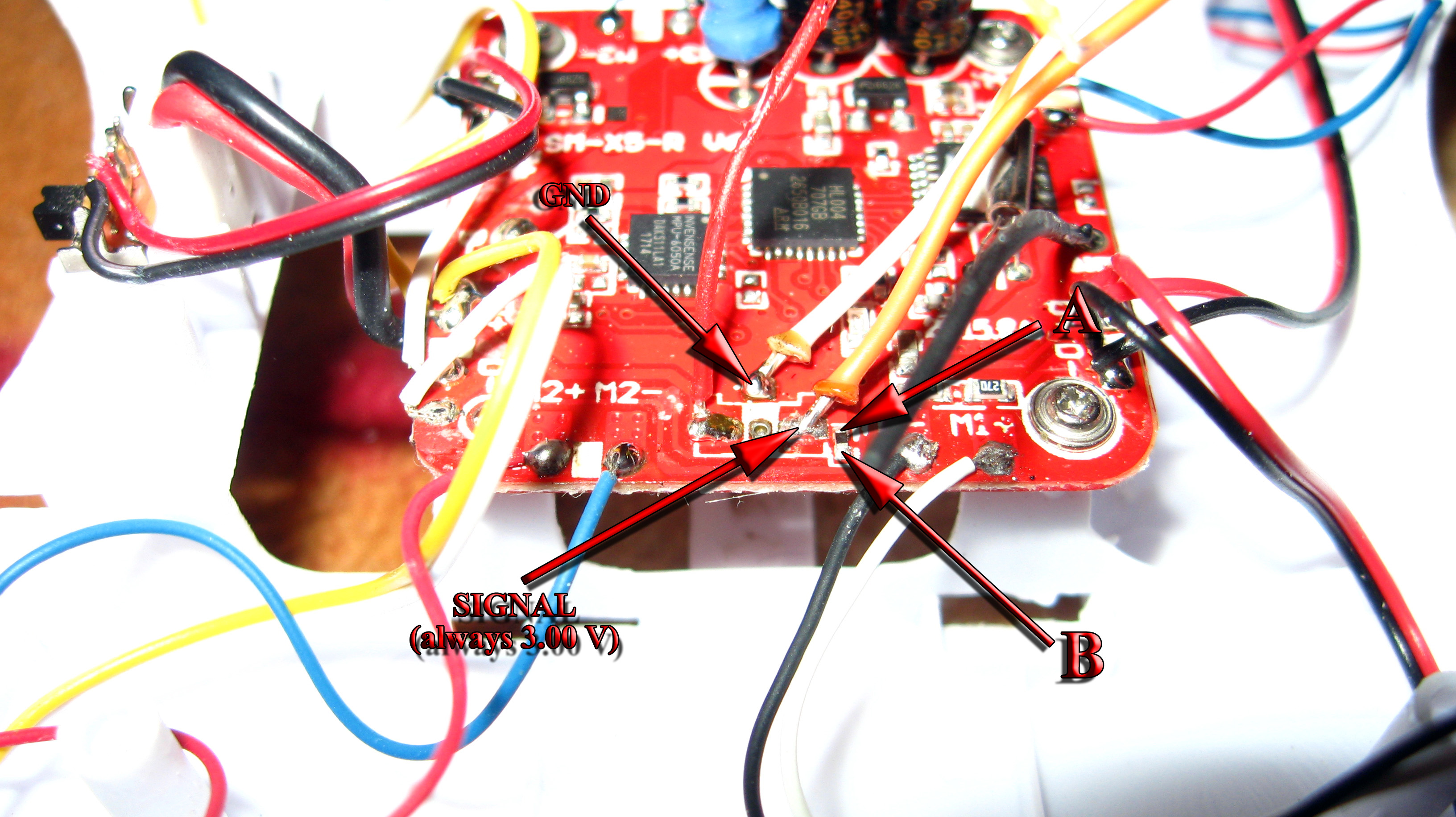
I have Syma X5 with board v6 and today I received the camera but I could't start the recording or take a photo. After checking the camera's PCB everything looked well so I opened the drone and soldered the wires to the PCB pads for yellow (SIGNAL) and black (GND) camera connector. From what I found online, the yellow output should upon activating the camera drop to GND for 0.25 seconds (photo) or 0.75 seconds (video) but the output is always 3.00 V.
Here is the picture. I have marked the GND and SIGNAL contacts of camera connector and the pads of what I believe to be the signal pull-up resistor (A is connected with SIGNAL and B is +3 V), however I measured that resistor as opened circuit (infinite resistance)!?
As I said, the board is V6 but I believe this might be an upgraded transmitter because it has
very long range - more than 275 m (900 ft). It has blue LED and I can receive the data with NRF24L01+ by using
symarx code. The only modification I had to make to the code is to
disable frequency hopping. What makes me to believe this is an upgraded transmitter is - there are functions that can be activated by long pressing the shoulder buttons. Upon long pressing the left shoulder button (rate) there are several long beeps and upon next long press of the left shoulder button there is one long beep. Upon long pressing the right shoulder button there are two short beeps. Unfortunatelly I (still) don't have logic analyzer to capture the SPI traffic when activating those functions but I am suspecting they are return to home and maybe altitude hold - which are, of course, not supported by Syma X5.
I would appreciate any help with not being able to activate the camera signal. Measured resistance of the resistor next to the signal contact might be very helpful - maybe I can fix the board by soldering another SMD resistor. And If I knew which µC pin is controlling the SIGNAL then I could check the trace and solder a wire if the trace is broken or check for a cold joint.