
- Posts: 776
Devo 7e - Voltage supply
- aMax
-
- Offline
Less
More
16 Aug 2016 17:42 - 16 Aug 2016 17:44 #52820
by aMax
On DSMX as well, 0.04 volt , because telemetry can` be switched off.......
Frsky V8= 0.0.0V to 0.03 and Frsky D8 depending on the transmisson power from 0.03 to 0.09 volt.
On Frsky V8 there is no fluctuation when you switch to this but after a cold start.
Devo7e, TaranisQ X7, R9M , 4in1 MM, Futaba FC18plusV3.2 & DFT/FLD-02
Replied by aMax on topic Devo 7e - Voltage supply
HappyHarry wrote: i just tested this and with the Frsky protocol my voltage fluctuates +/- 0.03v, but this happens with no other protocol, including Frsky-V8! have you posted a bug yet fernandez?
On DSMX as well, 0.04 volt , because telemetry can` be switched off.......
Frsky V8= 0.0.0V to 0.03 and Frsky D8 depending on the transmisson power from 0.03 to 0.09 volt.
On Frsky V8 there is no fluctuation when you switch to this but after a cold start.
Devo7e, TaranisQ X7, R9M , 4in1 MM, Futaba FC18plusV3.2 & DFT/FLD-02
Last edit: 16 Aug 2016 17:44 by aMax.
- Elmtree
-
- Offline
Less
More
- Posts: 60
20 Aug 2016 23:27 #52952
by Elmtree
Replied by Elmtree on topic Devo 7e - Voltage supply
So I just got by Devo 6s (which I'm excited about btw) and now the modding ideas must begin. So I will generally be using an LRS (openLRS) on this tx.
Fernandez, it looks like you replaced the 3.3V regulator directly with a pololu. Does the TX still work alright? besides the FRSKY voltage fluctuations. I don't plan on installing any other modules yet because the only 2.4ghz protocol I use is DSM. I just need to be able to run higher voltage batteries.
Fernandez, it looks like you replaced the 3.3V regulator directly with a pololu. Does the TX still work alright? besides the FRSKY voltage fluctuations. I don't plan on installing any other modules yet because the only 2.4ghz protocol I use is DSM. I just need to be able to run higher voltage batteries.
- robpur
-
- Offline
Less
More
- Posts: 47
21 Aug 2016 09:10 #52962
by robpur
Replied by robpur on topic Devo 7e - Voltage supply
If all you want to do is run a higher voltage battery without running additional RF modules, then connect your battery to a 5V switching regulator such as a Pololu, and then connect the regulator output to your TX. No need to modify your TX. The switching regulator will cut the battery pack voltage down to a level that will make the TX happy. There's no need to be fancy unless you need to boost the 3.3V supply to handle additional RF modules.
- Elmtree
-
- Offline
Less
More
- Posts: 60
21 Aug 2016 09:13 #52963
by Elmtree
Only issue is then I don't get voltage reading for the battery, just constant 5v. Ideas on how to remedy that? Can I add a jumper wire to the voltage divider somewhere? This would be an optimal solution for me because I already have tons of pololu 5v step downs
Replied by Elmtree on topic Devo 7e - Voltage supply
robpur wrote: If all you want to do is run a higher voltage battery without running additional RF modules, then connect your battery to a 5V switching regulator such as a Pololu, and then connect the regulator output to your TX. No need to modify your TX. The switching regulator will cut the battery pack voltage down to a level that will make the TX happy. There's no need to be fancy unless you need to boost the 3.3V supply to handle additional RF modules.
Only issue is then I don't get voltage reading for the battery, just constant 5v. Ideas on how to remedy that? Can I add a jumper wire to the voltage divider somewhere? This would be an optimal solution for me because I already have tons of pololu 5v step downs
- robpur
-
- Offline
Less
More
- Posts: 47
22 Aug 2016 19:41 #53012
by robpur
Replied by robpur on topic Devo 7e - Voltage supply
Yes, it would be possible to tie the voltage monitoring circuitry to your battery, but it could put your processor at risk. I only have a partial hand drawn schematic of the Devo power supply so I can't say anything for certain, but the schematic shows a voltage dividing resistor network attached to the power supply FET, which supplies voltage information to the processor. I assume that it's a direct connection without any buffering. If so, then breaking that circuity out to connect directly to the battery pack could be risky. If a static charge was ever put on the battery leads then it could damage the processor.
I've found the voltage readout of my 7E to be rather inaccurate, and the amount of error changes depending on the voltage being measured, so I don't depend on it. You could use a LiPo voltage monitor instead. It would not be as elegant as the internal volt meter, but it would be more accurate.
I've found the voltage readout of my 7E to be rather inaccurate, and the amount of error changes depending on the voltage being measured, so I don't depend on it. You could use a LiPo voltage monitor instead. It would not be as elegant as the internal volt meter, but it would be more accurate.
- Fernandez
-
- Offline
Less
More
- Posts: 983
22 Aug 2016 20:22 - 22 Aug 2016 20:24 #53015
by Fernandez
Replied by Fernandez on topic Devo 7e - Voltage supply
@Elmtree, yes my tx works fine, with the pololu, but what I did I competely removed the small miniature 3v3 ldo, and put the pololu stepup down 3v3 in place.
Tx runs fine, for over a year, but still not fully happy as it did not solve my issues.......
I thought the very hot small ldo was the troubles for voltage fluctuations in my readout, but the new regulator did not change that......
I not really understand the power circuitry and still there is some fluctuations left such as when using FRsky protocol at full power, I can't get a hand on it....
At the time I also tried with the antenna to put close to pcb lanes to see if I could make worse the effect and find if it was RF induced noices, but could not put the finger on it.....
Would be great if someone could clarify this whole power circuit...
Last edit: 22 Aug 2016 20:24 by Fernandez.
- robpur
-
- Offline
Less
More
- Posts: 47
22 Aug 2016 23:18 - 23 Aug 2016 01:18 #53017
by robpur
I'll take a stab at how the power circuit works based on the schematic I have. I believe the schematic was drawn and posted by PB, and it is based on a Devo 8. The 7E is said to be very similar, but might not be an exact match.
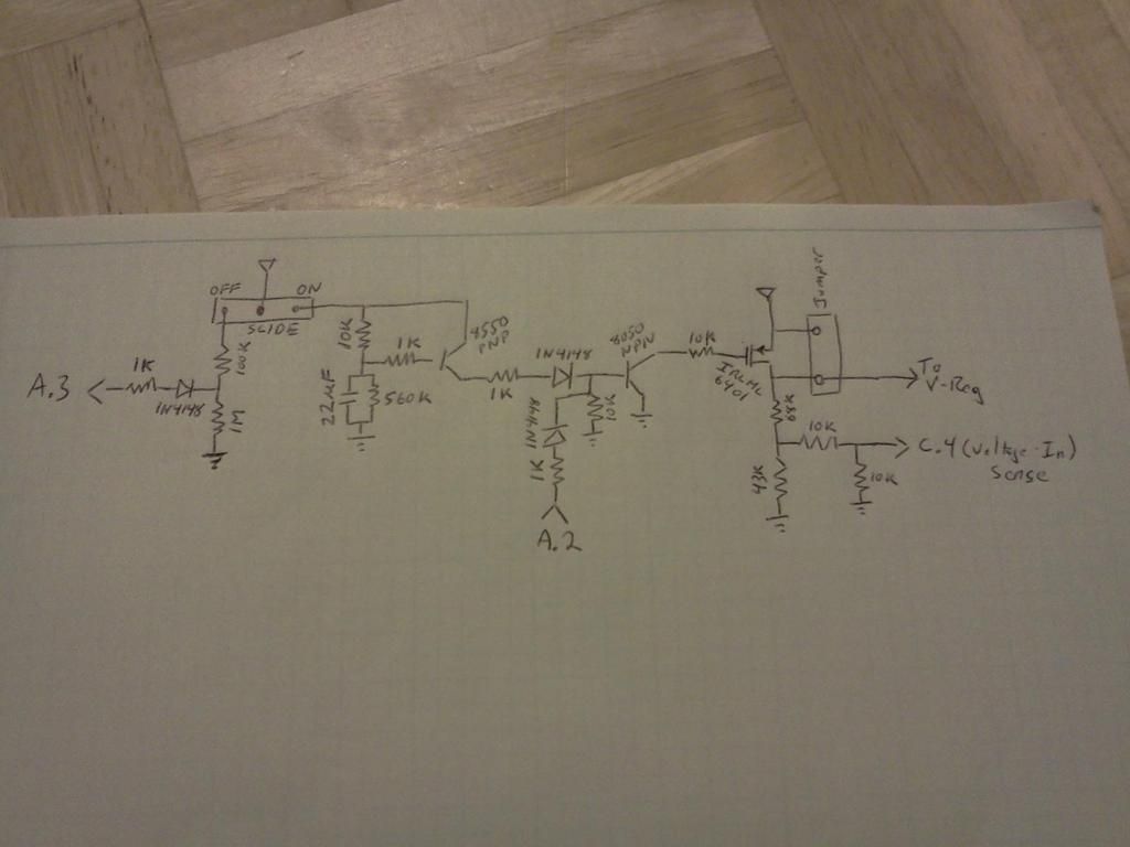
With the power switch on, the FET is on and power is supplied to the onboard 3.3V regulator (To V-Reg). There’s a voltage divider network made up of four resistors that lowers the battery voltage to a range that can then be read by the processor, C.4 (Voltage In Sense). The schematic does not show anything beyond this point, so it’s unclear if a connection is made directly to the processor without any other components.
While the power switch is on, A.3 is pulled low, and A.2 floats. I don’t know what A.2 is used for, but A.3 is likely used to signal the processor that power is going down. Switching power off allows A.3 to float which most likely tells the firmware to save settings. After the power switch is turned off, the FET is held on for a period of time by the 22uf capacitor which is drained by the 560k resistor. This keeps power on for a short period of time so the settings can be saved. The two transistors not only drive the FET, but they also provide an opportunity to pull A.2 low when power is off. I don’t have a clue what A.2 is used for.
My first thought on your volt meter bounce was noise from your switching supply, but it appears others are having the same problem with unmodified power supplies, which could point toward a firmware cause. However, my 7E voltage display doesn’t bounce no matter what protocol I use. I wonder if there’s a variation in the manufacturing of the TX that could be causing it for some, and not for others.
The first step to diagnose the problem is to look at the pin used to sense battery voltage with an oscilloscope. If the voltage is stable with no noise, then the problem is somewhere downstream in the digital domain. If there’s noise or fluctuating voltage at the sensing pin, then it’s an analog problem. If noise is found on the sensing pin then filtering would been needed, or the source of the noise identified and suppressed. If there’s fluctuating voltage, then tracing back through the analog circuitry would reveal the source.
One thought I’ve had on why mine does not fluctuate is that I have beefed up grounding. Power wires are only half the circuit so I often increase grounding when messing with power circuits. I removed some of the solder mask next to the power connector and soldered on two ground wires. One goes to the Pololu and the other goes to the RF shield on the CRYF module. I have two more ground wires that run from the shield to the 3in1 module. Ground loops can cause difficult to diagnose problems so I try to avoid them with additional ground strapping.
Replied by robpur on topic Devo 7e - Voltage supply
Fernandez wrote: Would be great if someone could clarify this whole power circuit...
I'll take a stab at how the power circuit works based on the schematic I have. I believe the schematic was drawn and posted by PB, and it is based on a Devo 8. The 7E is said to be very similar, but might not be an exact match.

With the power switch on, the FET is on and power is supplied to the onboard 3.3V regulator (To V-Reg). There’s a voltage divider network made up of four resistors that lowers the battery voltage to a range that can then be read by the processor, C.4 (Voltage In Sense). The schematic does not show anything beyond this point, so it’s unclear if a connection is made directly to the processor without any other components.
While the power switch is on, A.3 is pulled low, and A.2 floats. I don’t know what A.2 is used for, but A.3 is likely used to signal the processor that power is going down. Switching power off allows A.3 to float which most likely tells the firmware to save settings. After the power switch is turned off, the FET is held on for a period of time by the 22uf capacitor which is drained by the 560k resistor. This keeps power on for a short period of time so the settings can be saved. The two transistors not only drive the FET, but they also provide an opportunity to pull A.2 low when power is off. I don’t have a clue what A.2 is used for.
My first thought on your volt meter bounce was noise from your switching supply, but it appears others are having the same problem with unmodified power supplies, which could point toward a firmware cause. However, my 7E voltage display doesn’t bounce no matter what protocol I use. I wonder if there’s a variation in the manufacturing of the TX that could be causing it for some, and not for others.
The first step to diagnose the problem is to look at the pin used to sense battery voltage with an oscilloscope. If the voltage is stable with no noise, then the problem is somewhere downstream in the digital domain. If there’s noise or fluctuating voltage at the sensing pin, then it’s an analog problem. If noise is found on the sensing pin then filtering would been needed, or the source of the noise identified and suppressed. If there’s fluctuating voltage, then tracing back through the analog circuitry would reveal the source.
One thought I’ve had on why mine does not fluctuate is that I have beefed up grounding. Power wires are only half the circuit so I often increase grounding when messing with power circuits. I removed some of the solder mask next to the power connector and soldered on two ground wires. One goes to the Pololu and the other goes to the RF shield on the CRYF module. I have two more ground wires that run from the shield to the 3in1 module. Ground loops can cause difficult to diagnose problems so I try to avoid them with additional ground strapping.

Last edit: 23 Aug 2016 01:18 by robpur.
- Fernandez
-
- Offline
Less
More
- Posts: 983
23 Aug 2016 20:37 #53048
by Fernandez
Replied by Fernandez on topic Devo 7e - Voltage supply
It is certainly not the voltage fluctuation at the sense pin to the CPU, as I tested this by applying a large capacitor. To the pin and ground.
After switch on tx I see the tx voltage slowly come up took a few seconds to charge the capacitor, strange enough once charged stilll the voltage readout contain same fluctuations visible.
After switch on tx I see the tx voltage slowly come up took a few seconds to charge the capacitor, strange enough once charged stilll the voltage readout contain same fluctuations visible.
- robpur
-
- Offline
Less
More
- Posts: 47
24 Aug 2016 00:14 #53055
by robpur
Replied by robpur on topic Devo 7e - Voltage supply
So we are still in the same place. A scope would still need to be put on the sensing processor pin to look for noise. If there's no noise, then the problem is most likely in the digital domain. This assumes proper ground. Without doing proper measurements then diagnosis becomes a guessing game.
- Fernandez
-
- Offline
Less
More
- Posts: 983
24 Aug 2016 09:32 #53069
by Fernandez
Replied by Fernandez on topic Devo 7e - Voltage supply
The ADC pin is definitively clean, but the reference voltage for this adc, I think it is the 3V3 cpu voltage, so I expect that putting some big capacitors at VCC around the CPU might fix it. It is not clear if CPU and modules etc are wired all in paralle to same regulator. placing large capacitor at my modules does not solve. placing capacitor close to ARM CPU VCC lines I did not try it.
Another issue might be RFI, also here in TX design I believe is best close to cpu put some ceramic capacitors close to CPU, to short all RFI noise pick up. there is some reports people using 433mHz 1 watt ULRS and the Tx starts to ac weird due to RF.
Another issue might be RFI, also here in TX design I believe is best close to cpu put some ceramic capacitors close to CPU, to short all RFI noise pick up. there is some reports people using 433mHz 1 watt ULRS and the Tx starts to ac weird due to RF.
- bianchifan
-
Topic Author
- Offline
Less
More
- Posts: 49
30 Aug 2016 11:58 - 30 Aug 2016 12:01 #53276
by bianchifan
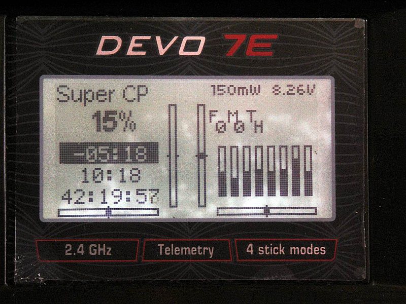
With the actual nightly my devo shows the current battery voltage..
Replied by bianchifan on topic Devo 7e - Voltage supply
Elmtree wrote: Only issue is then I don't get voltage reading for the battery, just constant 5v
With the actual nightly my devo shows the current battery voltage..
Last edit: 30 Aug 2016 12:01 by bianchifan.
- Elmtree
-
- Offline
Less
More
- Posts: 60
04 Sep 2016 20:29 #53472
by Elmtree
So I'm confused, where in the circuit is your 5v reg? I have the 6s not the 7e, so I'm having trouble figuring out where things go exactly
Replied by Elmtree on topic Devo 7e - Voltage supply
bianchifan wrote:
Elmtree wrote: Only issue is then I don't get voltage reading for the battery, just constant 5v
With the actual nightly my devo shows the current battery voltage..
So I'm confused, where in the circuit is your 5v reg? I have the 6s not the 7e, so I'm having trouble figuring out where things go exactly
- bianchifan
-
- Offline
Less
More
- Posts: 49
05 Sep 2016 10:48 #53501
by bianchifan
Maybe Devo 6? and Devo 7e do share their PCB design..
I think I'd take a pic to make it more clear.
Replied by bianchifan on topic Devo 7e - Voltage supply
On my 7E there isn't any 5V regulator..Elmtree wrote: So I'm confused, where in the circuit is your 5v reg?
The copper layer tells me: Walkera DEVO-6F 2.0.. whatever that should be.Elmtree wrote: I have the 6s not the 7e, so I'm having trouble figuring out where things go exactly
Maybe Devo 6? and Devo 7e do share their PCB design..
I think I'd take a pic to make it more clear.
- Elmtree
-
- Offline
Less
More
- Posts: 60
05 Sep 2016 14:13 - 05 Sep 2016 14:14 #53511
by Elmtree
Oh, I thought that the picture on the first post was of a 5v buck reg put into a 7e.
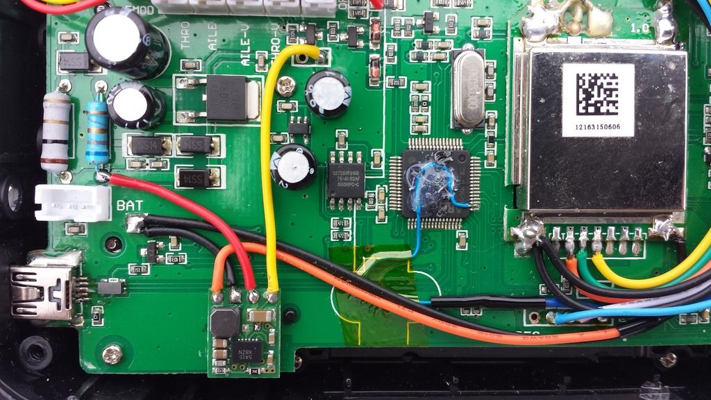
I'll take a pic of my 6s board layout ASAP, but for now, here's a picture of the 6s board. It's a large image so if you open it in a new tab you should be able to zoom in pretty far:

Replied by Elmtree on topic Devo 7e - Voltage supply
bianchifan wrote:
On my 7E there isn't any 5V regulator..Elmtree wrote: So I'm confused, where in the circuit is your 5v reg?
The copper layer tells me: Walkera DEVO-6F 2.0.. whatever that should be.Elmtree wrote: I have the 6s not the 7e, so I'm having trouble figuring out where things go exactly
Maybe Devo 6? and Devo 7e do share their PCB design..
I think I'd take a pic to make it more clear.
Oh, I thought that the picture on the first post was of a 5v buck reg put into a 7e.
I'll take a pic of my 6s board layout ASAP, but for now, here's a picture of the 6s board. It's a large image so if you open it in a new tab you should be able to zoom in pretty far:
Last edit: 05 Sep 2016 14:14 by Elmtree.
- bianchifan
-
- Offline
Less
More
- Posts: 49
06 Sep 2016 18:55 #53551
by bianchifan
I also wrote, that I stripped my LDO so the buck REPLACES it.
Later I wrote in another statement, that it may be a good idea to feed a better LDO than the inbuild one for smallest ripple.
To be independent from the input (Lipo/NiMH) I recommended 3.6 V.But last weekend I discoverd I was a little bit lazy, the battery input feeds a little more...
1. buzzer
2. vibrator
3. build in RF-TX module
4. display
All these have to work with the higher voltage..
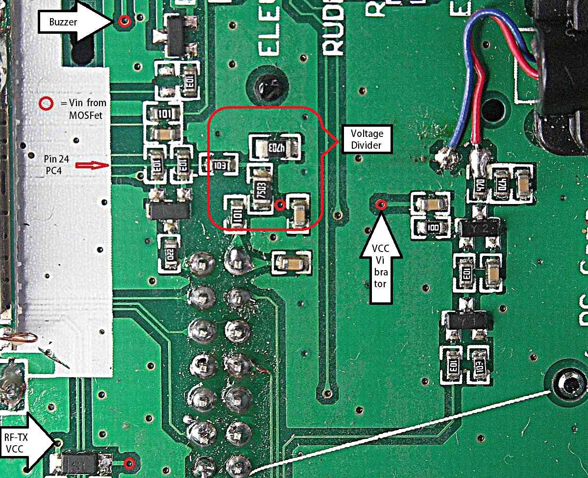
Nevertheless the MCU is reading the battery voltage, the divider 470K+750k is connected via 10k to Pin 24, PC4/ADC12_IN14.
470/(470+750) = 0.385
8.4V X .385 = 3.234 V...Uff (some months ago I fried an STM32-ADC with 5V.. real magic smoke 'cause no visible damage)
Replied by bianchifan on topic Devo 7e - Voltage supply
Ok..so your's is pretty differentElmtree wrote: ..here's a picture of the 6s board
I tried to show the scopes of two 3V3-trimmed Step-Downs at two input voltages, 5V2-NiMH and 8.4-LiPo open output'.Elmtree wrote: Oh, I thought that the picture on the first post was of a 5v buck reg put into a 7e.
I also wrote, that I stripped my LDO so the buck REPLACES it.
Later I wrote in another statement, that it may be a good idea to feed a better LDO than the inbuild one for smallest ripple.
To be independent from the input (Lipo/NiMH) I recommended 3.6 V.But last weekend I discoverd I was a little bit lazy, the battery input feeds a little more...
1. buzzer
2. vibrator
3. build in RF-TX module
4. display
All these have to work with the higher voltage..
Nevertheless the MCU is reading the battery voltage, the divider 470K+750k is connected via 10k to Pin 24, PC4/ADC12_IN14.
470/(470+750) = 0.385
8.4V X .385 = 3.234 V...Uff (some months ago I fried an STM32-ADC with 5V.. real magic smoke 'cause no visible damage)
- Elmtree
-
- Offline
Less
More
- Posts: 60
06 Sep 2016 19:05 #53552
by Elmtree
Ahh, I see what you did now. So I guess based on what the battery is powering it would be best to insert a 5v reg directly from the battery, then if I'm feeling ambitious cut the voltage divider trace and run a wire from the battery to the voltage divider.
Replied by Elmtree on topic Devo 7e - Voltage supply
bianchifan wrote:
Ok..so your's is pretty differentElmtree wrote: ..here's a picture of the 6s board
I tried to show the scopes of two 3V3-trimmed Step-Downs at two input voltages, 5V2-NiMH and 8.4-LiPo open output'.Elmtree wrote: Oh, I thought that the picture on the first post was of a 5v buck reg put into a 7e.
I also wrote, that I stripped my LDO so the buck REPLACES it.
Later I wrote in another statement, that it may be a good idea to feed a better LDO than the inbuild one for smallest ripple.
To be independent from the input (Lipo/NiMH) I recommended 3.6 V.But last weekend I discoverd I was a little bit lazy, the battery input feeds a little more...
1. buzzer
2. vibrator
3. build in RF-TX module
4. display
All these have to work with the higher voltage..
Nevertheless the MCU is reading the battery voltage, the divider 470K+750k is connected via 10k to Pin 24, PC4/ADC12_IN14.
470/(470+750) = 0.385
8.4V X .385 = 3.234 V...Uff (some months ago I fried an STM32-ADC with 5V.. real magic smoke 'cause no visible damage)
Ahh, I see what you did now. So I guess based on what the battery is powering it would be best to insert a 5v reg directly from the battery, then if I'm feeling ambitious cut the voltage divider trace and run a wire from the battery to the voltage divider.
- Fernandez
-
- Offline
Less
More
- Posts: 983
18 Oct 2016 11:45 - 18 Oct 2016 11:46 #55090
by Fernandez
Replied by Fernandez on topic Devo 7e - Voltage supply
Hey guys one more issue to report, I still use the pololu step up/down, to replace the small 100ma 3v3 LDO. It runs fine, when battery is getting low pololu still provides 3v3 even on low vbat and Tx still rus fine, however I can not anymore switch of the Tx.
So switching off the transmitter at low battery voltage, the 7e and display stay on, does not power off.
I like to use my 7e with up down and be able to run from single lipo cell, but then can't anymore switch off.
I do not like, the strange power circuitry, with many components as drawn above.....
a) The Polulo SHDN pin, with an R/C connected, could function as a delayed switch off, to switch off the Tx?
b) We only need 1 small mosfet, direct to the battery (before regulator) to the Resistor divider to show Vbat at tx, ADC pin. Maybe put a variable resistor to get V monitoring spot on. The mosfet gate can be switched with resistor, direct from the 3v3 output of pololu.
One more question how does CPU know, it will be switched off and must save it's settings at exit?
With this in place we can bypass the whole 7e power circuitry and power it with any battery of choice?
Last edit: 18 Oct 2016 11:46 by Fernandez.
- dropax
-
- Offline
Less
More
- Posts: 13
11 Mar 2017 00:29 #60106
by dropax
Hi!
Late but nevertheless:
Note the arrows indicating that A.3 in an input and A.2 an output. A.3 signals the CPU that it should shitdown, A.2 is held high until eeprom is written, beep and vibration done and the pulled low to cut the supply. I think the cap is to debounce the switch.
Anyway, I came here searching for a reason to my 7e shutting down randomly on it's own - no fun when this happens while flying...
Running NRF24L01 and A7105 modules from a 2s LiFePo it happened a couple of times using the range modded stock module with DSMX (which is what I use by far the most). I also noticed dictinctly reduced range on DSM wkth different receivers.
Now the question is if those two problems are related due to the devo's voltage regulator degrading or are the independent and the range issue comes from either hardware of the module of is even firmware related?
I want to replace the main regulator just to be sure, is it the 5-pin SOT23 between the two electrolytic caps?
Replied by dropax on topic Devo 7e - Voltage supply
robpur wrote:
Fernandez wrote: Would be great if someone could clarify this whole power circuit...
I'll take a stab at how the power circuit works based on the schematic I have. I believe the schematic was drawn and posted by PB, and it is based on a Devo 8. The 7E is said to be very similar, but might not be an exact match.
With the power switch on, the FET is on and power is supplied to the onboard 3.3V regulator (To V-Reg). There’s a voltage divider network made up of four resistors that lowers the battery voltage to a range that can then be read by the processor, C.4 (Voltage In Sense). The schematic does not show anything beyond this point, so it’s unclear if a connection is made directly to the processor without any other components.
While the power switch is on, A.3 is pulled low, and A.2 floats. I don’t know what A.2 is used for, but A.3 is likely used to signal the processor that power is going down. Switching power off allows A.3 to float which most likely tells the firmware to save settings. After the power switch is turned off, the FET is held on for a period of time by the 22uf capacitor which is drained by the 560k resistor. This keeps power on for a short period of time so the settings can be saved. The two transistors not only drive the FET, but they also provide an opportunity to pull A.2 low when power is off. I don’t have a clue what A.2 is used for.
...
Hi!
Late but nevertheless:
Note the arrows indicating that A.3 in an input and A.2 an output. A.3 signals the CPU that it should shitdown, A.2 is held high until eeprom is written, beep and vibration done and the pulled low to cut the supply. I think the cap is to debounce the switch.
Anyway, I came here searching for a reason to my 7e shutting down randomly on it's own - no fun when this happens while flying...
Running NRF24L01 and A7105 modules from a 2s LiFePo it happened a couple of times using the range modded stock module with DSMX (which is what I use by far the most). I also noticed dictinctly reduced range on DSM wkth different receivers.
Now the question is if those two problems are related due to the devo's voltage regulator degrading or are the independent and the range issue comes from either hardware of the module of is even firmware related?
I want to replace the main regulator just to be sure, is it the 5-pin SOT23 between the two electrolytic caps?
- Wene001
-
- Offline
Less
More
- Posts: 277
11 Mar 2017 07:57 - 11 Mar 2017 08:01 #60113
by Wene001
Replied by Wene001 on topic Devo 7e - Voltage supply
i had this problem with Devo12s and a cc2500 from banggood, and looked at it with my scope.
www.deviationtx.com/forum/3-feedback-que...voltage?limitstart=0
The Modules have pulsing power consumption (Frsky is worst) , and are messing up the internal 3,3V power line.
All analog input readings and reference voltage for Battery Voltage reading are fluctuating.
The Original Cyrf Modul has an onboard LDO, so have the 4in1(especially for Devo)
With these Modules all is fine.
The problem is only when using the internal 3,3V line to power a TX Module.
(Polulu or not)
Now i´m using the Battery Voltage Pin on the Original Module Header with an second LDO to power the modules (which i hacked in)
Silence on all analog Stick and pots reading, and the TX Voltage Display.
Works fine on my Devo12s, Devo8s, Devo6s
Last edit: 11 Mar 2017 08:01 by Wene001. Reason: Link is working now
- robocog
-
- Offline
12 Mar 2017 00:27 #60137
by robocog
I cannot offer much in the way of assistance yet but I do know that A3 needs to be grounded for USB removable device to work, A2 on the hardware wiki shows it outputs 0 to turn the TX off
so A3 is an input and A2 is an output according to the wiki
I'm playing with a couple of dev boards and trying to get them working with deviation and have had some fantastic assistance
The PSU and switching stage I think is going to be next on the list to try and decipher and get working on the dev boards
The thread is here
Regards
Rob
Replied by robocog on topic Devo 7e - Voltage supply
dropax wrote:
robpur wrote:
Fernandez wrote: Would be great if someone could clarify this whole power circuit...
I'll take a stab at how the power circuit works based on the schematic I have. I believe the schematic was drawn and posted by PB, and it is based on a Devo 8. The 7E is said to be very similar, but might not be an exact match.
With the power switch on, the FET is on and power is supplied to the onboard 3.3V regulator (To V-Reg). There’s a voltage divider network made up of four resistors that lowers the battery voltage to a range that can then be read by the processor, C.4 (Voltage In Sense). The schematic does not show anything beyond this point, so it’s unclear if a connection is made directly to the processor without any other components.
While the power switch is on, A.3 is pulled low, and A.2 floats. I don’t know what A.2 is used for, but A.3 is likely used to signal the processor that power is going down. Switching power off allows A.3 to float which most likely tells the firmware to save settings. After the power switch is turned off, the FET is held on for a period of time by the 22uf capacitor which is drained by the 560k resistor. This keeps power on for a short period of time so the settings can be saved. The two transistors not only drive the FET, but they also provide an opportunity to pull A.2 low when power is off. I don’t have a clue what A.2 is used for.
...
Hi!
Late but nevertheless:
Note the arrows indicating that A.3 in an input and A.2 an output. A.3 signals the CPU that it should shitdown, A.2 is held high until eeprom is written, beep and vibration done and the pulled low to cut the supply. I think the cap is to debounce the switch.
Anyway, I came here searching for a reason to my 7e shutting down randomly on it's own - no fun when this happens while flying...
Running NRF24L01 and A7105 modules from a 2s LiFePo it happened a couple of times using the range modded stock module with DSMX (which is what I use by far the most). I also noticed dictinctly reduced range on DSM wkth different receivers.
Now the question is if those two problems are related due to the devo's voltage regulator degrading or are the independent and the range issue comes from either hardware of the module of is even firmware related?
I want to replace the main regulator just to be sure, is it the 5-pin SOT23 between the two electrolytic caps?
I cannot offer much in the way of assistance yet but I do know that A3 needs to be grounded for USB removable device to work, A2 on the hardware wiki shows it outputs 0 to turn the TX off
so A3 is an input and A2 is an output according to the wiki
I'm playing with a couple of dev boards and trying to get them working with deviation and have had some fantastic assistance
The PSU and switching stage I think is going to be next on the list to try and decipher and get working on the dev boards
The thread is here
Regards
Rob
Time to create page: 0.054 seconds
-
Home

-
Forum
-
General
-
General Discussions
- Devo 7e - Voltage supply