
- Posts: 95
Adding switches to devo 6s
- dado099
-
Topic Author
- Offline
Less
More
20 Aug 2013 14:34 #13048
by dado099
Adding switches to devo 6s was created by dado099
Hello everyone,
it's a lot of time that I have this question to put here:
Is it possible to add one or two more switches to this TX ?
I think mechanically yes, but where should I solder them to TX board
to feed ch 7 and 8 ?
Any clues ?
Thanks
it's a lot of time that I have this question to put here:
Is it possible to add one or two more switches to this TX ?
I think mechanically yes, but where should I solder them to TX board
to feed ch 7 and 8 ?
Any clues ?
Thanks
- rbe2012
-
- Offline
- So much to do, so little time...
Less
More
- Posts: 1433
26 Aug 2013 13:12 #13306
by rbe2012
Replied by rbe2012 on topic Adding switches to devo 6s
mechanically: yes
electrically: probably (might need some fine soldering)
deviationally: there will be no way to integrate additional switches in the main deviation line. If you want to support the additional switches, a fork of deviation is necessary (with all implications like needing a developer, taking care of integration new deviation features in the fork, synchronize the development with the main line...). We have a discussion somewhere else about additional switches for Devo7e and it works this way (there was a volunteer who maintains the software). This is one of the benefits of OpenSource software -you can use it as you want, even write your own code on this base...
- dado099
-
- Offline
Less
More
- Posts: 95
26 Aug 2013 15:08 #13310
by dado099
Replied by dado099 on topic Adding switches to devo 6s
Thank you very much for your clarifications ! ")
- RoGuE_StreaK
-
- Offline
Less
More
- Posts: 486
21 Sep 2015 04:15 #37914
by RoGuE_StreaK
Replied by RoGuE_StreaK on topic Adding switches to devo 6s
Any updates on this? With the changes in the 7E methodologies over the past few years, should the 6s be able to have switches added without custom publishing?
Anyone know how the guts of the 6s differs from the 8s? I've just read several things saying they are "essentially" the same TX in different sized cases, so got me thinking as to whether it would be a "simple" matter to add some of the extra switches/dials that the 8s has?
Anyone know how the guts of the 6s differs from the 8s? I've just read several things saying they are "essentially" the same TX in different sized cases, so got me thinking as to whether it would be a "simple" matter to add some of the extra switches/dials that the 8s has?
- mwm
-
- Offline
21 Sep 2015 05:33 - 21 Sep 2015 05:34 #37916
by mwm
Do not ask me questions via PM. Ask in the forums, where I'll answer if I can.
My remotely piloted vehicle ("drone") is a yacht.
Replied by mwm on topic Adding switches to devo 6s
Well, there are two things of interest here. First, we now support additional switches on the 7e in the stock build, so changing the software to support them on a 6s is probably easier than it used to be. In fact, if you can work out a method within my rather limited hardware skills (I bought a 6s in order to avoid the 7e hardware mods), I'd be willing to take a shot at building firmware to support it.
Second, there's been a lot of work on adding inputs that connect to an arduino that uses the existing ppm input functionality. These will work on any supported Tx that has a trainer port, require no software mods, and can even be done with no hardware mods. The downside is that since they use the ppm input, at the very least they interact with other things that want to use it. See deviationtx.com/forum/7-development/4442...inputs-for-devo-tx-s for details.
Second, there's been a lot of work on adding inputs that connect to an arduino that uses the existing ppm input functionality. These will work on any supported Tx that has a trainer port, require no software mods, and can even be done with no hardware mods. The downside is that since they use the ppm input, at the very least they interact with other things that want to use it. See deviationtx.com/forum/7-development/4442...inputs-for-devo-tx-s for details.
Do not ask me questions via PM. Ask in the forums, where I'll answer if I can.
My remotely piloted vehicle ("drone") is a yacht.
Last edit: 21 Sep 2015 05:34 by mwm.
- RoGuE_StreaK
-
- Offline
Less
More
- Posts: 486
21 Sep 2015 23:47 #37940
by RoGuE_StreaK
Replied by RoGuE_StreaK on topic Adding switches to devo 6s
Hi Mike
Yep I'm aware of the Additional Inputs thread, and will keep an eye on it, but was interested to see if there was anything sitting there unused in stock format first.
I pulled apart the 6s last night (well, to a degree), and just under the module there are three interesting looking blank ports, two of which look extremely likely; "hov p" and "hov t". From how I understand it, these could well be trim buttons for Hover Pitch and Hover Throttle, so maybe(!) you could throw in a momentary on/off/on rocker/toggle (maybe like this one ), throw in some virtual channels, and have two new switches?
Can anyone confirm the layout of a typical trim switch? From what I've found, appears to be two momentary buttons with a rocker arm, guessing for three-pin connector that central pin is common then side pins are the "on" state for each direction?
Mike, I can probably cobble together one test "trim" like this as a test, if you can enable the code to suit? Then if it works, I'd look at getting a couple of "proper" toggles to install.
Alternately, if that is the physical setup for a trim, could it be coded to allow a three-position switch instead?
No idea what "P19" could be for. Wonder if they are common descriptors across the range?
- mwm
-
- Offline
22 Sep 2015 21:19 #37976
by mwm
Do not ask me questions via PM. Ask in the forums, where I'll answer if I can.
My remotely piloted vehicle ("drone") is a yacht.
Replied by mwm on topic Adding switches to devo 6s
No clue what the P19 thing might be.
The Tx's I've seen with Hover Pitch and Hover Throttle controls had knobs, not trims. That would actually be a major win, as the connections are simpler: ground, power and something tied directly to an MCU pin, with no button matrix to sort through. And frankly, I'd rather have a couple of extra analog inputs than a switch. Or even two. Downside is they will require calibration. But yeah, that should be simple to add and I'd love to have them, so I'm up for hacking the software for it.
Since you've got yours open (and I hate opening my tx's), can you check what type of MCU it has? Hopefully, it's the STM32F103VCT6 used in the 10 and 8. If not, let us know what it is. Then ping all the points involved, and figure out which MCU pins those are connected to. If it's a STM32F103VCT6, try pins 15 & 29, as those are AUX4 and AUX5 on the 10. If it's some other CPU, chase down the pinout and try PC0 and PA4 first. If those fail, try the rest of the ADC pins.
If you don't want to sort through the data sheets to give me pin names, can you get a photo good enough to read the labels on, and tag which pins are tied to which inputs?
Since I've got it open, here's the datasheet on the STM32F103VCT6 www.st.com/st-web-ui/static/active/en/re...sheet/CD00191185.pdf .
Do not ask me questions via PM. Ask in the forums, where I'll answer if I can.
My remotely piloted vehicle ("drone") is a yacht.
- RoGuE_StreaK
-
- Offline
Less
More
- Posts: 486
22 Sep 2015 23:14 #37977
by RoGuE_StreaK
Replied by RoGuE_StreaK on topic Adding switches to devo 6s
Didn't stay open long, just opened her up, took some photos, and closed her again; very simple and painless, just pop off the rubber grips and undo five hex bolts ") Then if you want a better look under the module it's just two phillips head screws.
Then if you want a better look under the module it's just two phillips head screws.
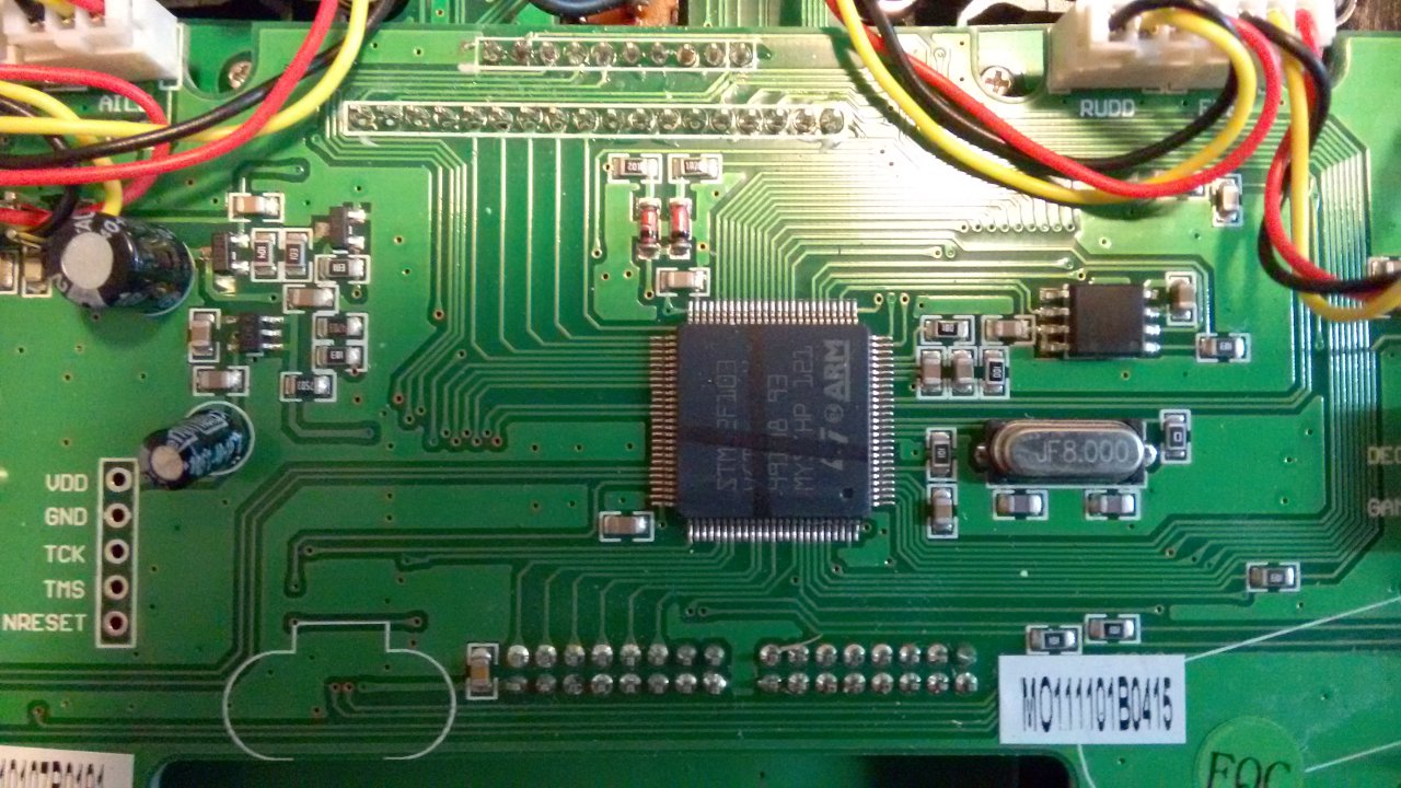
Can't quite tell the MCU in the photos as there's a black texta mark across it, first line is definitely "STM32F103", second is very likely "VCT" but the number is covered. Pretty sure they are the same MCUs though from what PB has said in the past?
If you look at photos of the 8(s), 10, and 12(s), they all have trims beside the top switches, and this is what I'm basing my assumption on, especially as the 8 doesn't have knobs. Maybe on Friday I might be able to do some tracing of sorts.
- RoGuE_StreaK
-
- Offline
Less
More
- Posts: 486
23 Sep 2015 03:01 - 23 Sep 2015 03:07 #37985
by RoGuE_StreaK
Replied by RoGuE_StreaK on topic Adding switches to devo 6s
A couple of things I've found browsing which may or may not be of interest;
- doing an extremely rough comparison of (bad) photos from my 6s board to some (bad) photos of the 8s board, one thing that became apparent to me is that the 6s has pin 53 (PB3) of the MCU going off somewhere, whereas the 8s has no such trace?
8s board
another 8s board
and another
see how down the "bottom" there's a big gap and then two traces, gap, two traces, gap, one trace? On the 6s, that first grouping has three traces?
No idea what that means...
- Here's another bit of an 8s, showing two boards off the sides (presumable the extra trims) with three-wire connectors; one seems to have the word "PIT" on it
side boards
PS. I should say that the 6s is more of a "stacked" PCB construction than the full-sized TX's, but I haven't unscrewed the boards yet to see what lies beneath. That is starting to get into the realms of too much risk vs not enough reward, when there's no real reason to go delving in yet.
Last edit: 23 Sep 2015 03:07 by RoGuE_StreaK. Reason: extra photo of entire TX
- mwm
-
- Offline
23 Sep 2015 04:39 #37999
by mwm
Do not ask me questions via PM. Ask in the forums, where I'll answer if I can.
My remotely piloted vehicle ("drone") is a yacht.
Replied by mwm on topic Adding switches to devo 6s
I don't think the last digit matters. The STM32F013VC pinpoints the package for us, among other things.
PB3 is also used in the JTAG debug interface; the extra trace could be related to that.
I went by the names - hover pitch and hover throttle are generally knobs used on older helis. If it's a pair of buttons with a shared input, then two of them will trace back to mcu pins instead of just one, and they'll trace back to pins that are in the button matrix. In fact, the source for the buttons on the 6 and 8 is identical, except that the four buttons for those trims are disabled in the 6 version. So they may well be connected to the same pins in the 6 as they are in the 8. If that's the case, turning them on should be easy.
If you're felling really ambitious, it'd be great to have something a hardware connections document for the 6. If you're not familiar with those, click "Articles", then "Hardware Documentation", then pick one at random. I'm not sure I could produce much of that myself. The 7E hardware connections list is where the "extra inputs" stuff started - someone noticed there were unused slots in the table, so just connected switches to connect to them.
Do not ask me questions via PM. Ask in the forums, where I'll answer if I can.
My remotely piloted vehicle ("drone") is a yacht.
- RoGuE_StreaK
-
- Offline
Less
More
- Posts: 486
24 Sep 2015 00:00 #38012
by RoGuE_StreaK

In which case, pin 83 (PD2) is available, like on the devo 8, so theoretically rbe2012's haptic motor hack could also be applied...
Replied by RoGuE_StreaK on topic Adding switches to devo 6s
My bad, it's actually pin 80 (PC12); I thought it was a 64 pin package, not 100 pinRoGuE_StreaK wrote: one thing that became apparent to me is that the 6s has pin 53 (PB3) of the MCU going off somewhere, whereas the 8s has no such trace?
In which case, pin 83 (PD2) is available, like on the devo 8, so theoretically rbe2012's haptic motor hack could also be applied...
- RoGuE_StreaK
-
- Offline
Less
More
- Posts: 486
25 Sep 2015 07:18 - 25 Sep 2015 07:27 #38043
by RoGuE_StreaK
Replied by RoGuE_StreaK on topic Adding switches to devo 6s
Well I had it fully apart today, and attempted to trace stuff but no luck; I think the issue is that I don't understand how the button matrix works. I was just trying to do a continuity test with a DMM, but got nowhere. Only thing I found was that the centre pin on P19 connects electrically to the black wires found on the toggle switches. However this didn't seem to be the case for the HOV-P and HOV-T spots.
HOV-P and HOV-T both share a common centre pin trace, and all unpopulated connectors (HOV-P, HOV-T, P19) have traces on all pads, going to somewhere.
Oh, and in sunlight I can see that the MCU is definitely a VTC6.
For later exhaustive analysis I have taken a buttload of photos (NB: metric buttload, not imperial; don't want imperial entanglements), I've tried to capture every trace I could see. Have to figure out a good place to put them.
While I was in there I replaces my broken FMOD switch with the new one that just arrived. In the process I found that "1", the centre position, occurs when there is no connection. Connecting one way or the other results in "0" or "2". Which then got me thinking, if these top HOV-P ad HOV-T positions are in fact trims, then theoretically they could be replaced with a 3-pos switch, on-off-on? I assume the differentiation between trim switches and a 3-pos is purely software, taking into account that one is momentary whilst the other latches?
Got a lot of analysis to do, and no time to do it
Last edit: 25 Sep 2015 07:27 by RoGuE_StreaK. Reason: more info on unpopulated connector traces
- mwm
-
- Offline
25 Sep 2015 15:11 #38057
by mwm
Do not ask me questions via PM. Ask in the forums, where I'll answer if I can.
My remotely piloted vehicle ("drone") is a yacht.
Replied by mwm on topic Adding switches to devo 6s
Each input on the button matrix connects a row pin (GPIOE 2-6) and a column pin (GPIOC 6-9). The column pins are turned on one at a time, and for each one, the row ports are checked to see which ones came on, indicating that the button connected to those two pins is down. The 6 and 8 have identical button matrices, except that GPIOB8 which is connected to the upper trims with one unused spot is completely unused on the 6.
Ok, I'm working through the connections while staring at the sources to try and figure out what you might be seeing. Sorry if the next bit is obvious.
Switches use one pin each, with 3-way switches being two pins for 0 & 2, with 1 being both on, with the switch connecting to either ground to go off or 3.3V to go on (from the source, it could be either way).
Analog inputs are connected to ground, 3.3V and a pin which will be in analog mode.
So if any of these are trim buttons, each should have an independent connection to one of the GPIOE pins, and a shared connection to a column pin, hopefully GIOB8. If P19 is connected to the button matrix, it could be connected to the last slot on GIOB8, or to GIOE5 & GIOB9, which is also unused. If they are unconnected switches, then one line should be shared between them and all the other switches, and the other two connected to arbitrary pins. The two switch pins that are used on the 8 but not the 6 are GPIOC 8 and 9. An analog input should have connections to power & ground and one to a pin independent of anything else.
So that HOV-P and HOV-T share a trace doesn't help much - it could be the shared column on the button matrix, or the non-pin side of a three-way switch, or the power or ground of an analog input. That P19 shares a connection with the toggle switches means it ISN'T connected to the button matrix. So my guess would be that the other two sides connect to GPIOC 8 and 9, and it can trivially be used as either a 3-way switch or a pair of 2-way switches.
And yes, a button is basically a momentary switch, a trim is two buttons and a three-way switch is two switches, and which is which just depends on the software. While the factory connects all us switches with independent pins and buttons via the matrix, the additional switches on the 7E go through the button matrix and show up as channels, not buttons. We could add them as "buttons" in the software, but the consensus seems to be that there are enough buttons since the up/down/left/right buttons are available for general use.
Is VTC6 a typo, and you actually mean VCT6? The latter is what we have in the 8 & 10.
Thanks for taking the time to do this!
Do not ask me questions via PM. Ask in the forums, where I'll answer if I can.
My remotely piloted vehicle ("drone") is a yacht.
- RoGuE_StreaK
-
- Offline
Less
More
- Posts: 486
27 Sep 2015 07:25 #38101
by RoGuE_StreaK
Replied by RoGuE_StreaK on topic Adding switches to devo 6s
Thanks mwm, haven't had much chance to look at this, but just had a slight glance over the photos;
Here's a list of MCU pins that don't seem to have traces from them; unfortunately the list includes pins 65 and 66, which from my reading of the datasheet are GPIOC8 and GPIOC9?
- 7,8,9, 14, 17,18, 23
- 27, 29, 33,34, 47,48
- 59,60, 63,64,65,66,67,68,69, 73
- 77,78,79, 83,84, 87, 89,90, 97,98
I'm not sure if your description of the 3-way functionality matches my physical switches; it seems to me that "1" is both off? Pretty sure most MCU designers prefer to use switching to ground?
Yep typo, VCT6
If I get some "free time" at work I might start trying to layering photos, see if I can get front'n'back traces to match up
- RoGuE_StreaK
-
- Offline
Less
More
- Posts: 486
28 Sep 2015 00:14 - 28 Sep 2015 01:13 #38129
by RoGuE_StreaK
Replied by RoGuE_StreaK on topic Adding switches to devo 6s
ON-the-fly update; checking out the photos, the centre pin of P19 and the black wires of the switches all go to the same plane, assumably a ground plane. Very rare/dumb to have a flood-fill plane carrying power (unless a separate core layer).
Inversely, the "hov-p" / "hov-t" centre pins are connected together and have a trace going off somewhere; very likely not connected to ground, so more likely connecting to the button matrix like the other trims...
Inversely, the "hov-p" / "hov-t" centre pins are connected together and have a trace going off somewhere; very likely not connected to ground, so more likely connecting to the button matrix like the other trims...
Actually should that be GPIOB 6-9, like the devo 8 doc says?mwm wrote: Each input on the button matrix connects a row pin (GPIOE 2-6) and a column pin (GPIOC 6-9)
Last edit: 28 Sep 2015 01:13 by RoGuE_StreaK.
- mwm
-
- Offline
28 Sep 2015 04:55 #38139
by mwm
Do not ask me questions via PM. Ask in the forums, where I'll answer if I can.
My remotely piloted vehicle ("drone") is a yacht.
Replied by mwm on topic Adding switches to devo 6s
You're right both times: the button matrix is the same as the Devo8 - I just goofed there. And the switches are both going to ground. I was looking at the switches represented in the software, where the test turns on the 1 position if the conditions for 2 and 0 are both true.
Do not ask me questions via PM. Ask in the forums, where I'll answer if I can.
My remotely piloted vehicle ("drone") is a yacht.
- RoGuE_StreaK
-
- Offline
Less
More
- Posts: 486
13 Oct 2015 11:43 #38774
by RoGuE_StreaK
Replied by RoGuE_StreaK on topic Adding switches to devo 6s
Sorry for the slowness, haven't had much chance to look at this. I got so far with the photos I had, and got some good leads, but then would reach parts where no photos covered (eg. overlapping boards). So armed with my notes, I just had a quick look tonight, not a full disassembly just a "pop the top".
There must be some internal stuff happening on some pins, as for the central positions of the switches and the P19 header, I get 830ohms continuity for PB8, PB9, PC12... so no idea where they actually connect to. Maybe someone can give some tips on ways to test continuity of these pins in circuit?
BUT, as far as "HOV-P" and "HOV-T" are concerned, I got pretty definitive continuity, and am almost certain that they are the same as the 8s; I believe central trace is PB8, HOV-T has switch traces to PE3 and PE4, and HOV-P has switch traces to PE5 and PE6. I should say that if these trims are enabled in the 6s build, a very simple hardware addition will result in a new pair of trims which can be used as either trims, toggles via virtual channels, or possibly 3-way physical switches if defined that way.
And now it's time for bed
There must be some internal stuff happening on some pins, as for the central positions of the switches and the P19 header, I get 830ohms continuity for PB8, PB9, PC12... so no idea where they actually connect to. Maybe someone can give some tips on ways to test continuity of these pins in circuit?
BUT, as far as "HOV-P" and "HOV-T" are concerned, I got pretty definitive continuity, and am almost certain that they are the same as the 8s; I believe central trace is PB8, HOV-T has switch traces to PE3 and PE4, and HOV-P has switch traces to PE5 and PE6. I should say that if these trims are enabled in the 6s build, a very simple hardware addition will result in a new pair of trims which can be used as either trims, toggles via virtual channels, or possibly 3-way physical switches if defined that way.
That doesn't seem to make sense from the hardware point of view, wouldn't it be if they were both false, as in neither are in the On position? Or maybe it's a reverse logic thing, where true = not connecting?mwm wrote: where the test turns on the 1 position if the conditions for 2 and 0 are both true.
And now it's time for bed
- mwm
-
- Offline
13 Oct 2015 21:14 #38781
by mwm
No problem - this is all a hobby for me, meaning the schedule is "when I feel like it". I expect nothing more from anyone else!
Unfortunately, it's someone who isn't me!
Yup, those are the connections for the two extra trims on the 8. Enabling them as trims with those names should be trivial. I don't think we even need to change the names like the 7E did. Extra switches is a bit more work, but certainly doable.
I think I've confused myself, because we've got buttons which go through a matrix, switches which short to ground, and channels, which is the value that shows up on the channel monitor. Buttons go through the matrix, so the pin and channel are both on when it connects. Switches short to ground, so the pin is off when connected and the corresponding channel value is on. The channel value for the middle position of a 3-way switch is on when the two pins that correspond to the end positions are on, meaning those two channels are off. Have I managed to confuse you now as well?
Do not ask me questions via PM. Ask in the forums, where I'll answer if I can.
My remotely piloted vehicle ("drone") is a yacht.
Replied by mwm on topic Adding switches to devo 6s
RoGuE_StreaK wrote: Sorry for the slowness, haven't had much chance to look at this. I got so far with the photos I had, and got some good leads, but then would reach parts where no photos covered (eg. overlapping boards). So armed with my notes, I just had a quick look tonight, not a full disassembly just a "pop the top".
No problem - this is all a hobby for me, meaning the schedule is "when I feel like it". I expect nothing more from anyone else!
There must be some internal stuff happening on some pins, as for the central positions of the switches and the P19 header, I get 830ohms continuity for PB8, PB9, PC12... so no idea where they actually connect to. Maybe someone can give some tips on ways to test continuity of these pins in circuit?
Unfortunately, it's someone who isn't me!
BUT, as far as "HOV-P" and "HOV-T" are concerned, I got pretty definitive continuity, and am almost certain that they are the same as the 8s; I believe central trace is PB8, HOV-T has switch traces to PE3 and PE4, and HOV-P has switch traces to PE5 and PE6. I should say that if these trims are enabled in the 6s build, a very simple hardware addition will result in a new pair of trims which can be used as either trims, toggles via virtual channels, or possibly 3-way physical switches if defined that way.
Yup, those are the connections for the two extra trims on the 8. Enabling them as trims with those names should be trivial. I don't think we even need to change the names like the 7E did. Extra switches is a bit more work, but certainly doable.
That doesn't seem to make sense from the hardware point of view, wouldn't it be if they were both false, as in neither are in the On position? Or maybe it's a reverse logic thing, where true = not connecting?[/quote]mwm wrote: where the test turns on the 1 position if the conditions for 2 and 0 are both true.
I think I've confused myself, because we've got buttons which go through a matrix, switches which short to ground, and channels, which is the value that shows up on the channel monitor. Buttons go through the matrix, so the pin and channel are both on when it connects. Switches short to ground, so the pin is off when connected and the corresponding channel value is on. The channel value for the middle position of a 3-way switch is on when the two pins that correspond to the end positions are on, meaning those two channels are off. Have I managed to confuse you now as well?
Do not ask me questions via PM. Ask in the forums, where I'll answer if I can.
My remotely piloted vehicle ("drone") is a yacht.
- RoGuE_StreaK
-
- Offline
Less
More
- Posts: 486
14 Oct 2015 00:15 - 14 Oct 2015 00:17 #38785
by RoGuE_StreaK
Not that I'm in any rush to mod.
2x On = 2x Off = On
Got it
Having a look again at PB's hardware docs, comparing the 8s with the 10, and then comparing the docs with various photos of the 8s boards I've found (linked above), I'm thinking either I'm not interpreting the datasheet pin diagrams/naming correctly, or PB's gotten something wrong? ie. for GPIOC, PB's got switches coming off 10, 11, and 12, but my interpretation is that these would be pins 78, 79, and 80, which from what I can see don't have traces on the 8s?
Left the lid off my TX at home, so might do some more probing tonight.
Replied by RoGuE_StreaK on topic Adding switches to devo 6s
Any issues with making that active by default, even if nothing is physically connected? Or will that show up on a trims page and people will get confused? Any "quick" way of adding a commentable "exists" config?mwm wrote: Yup, those are the connections for the two extra trims on the 8. Enabling them as trims with those names should be trivial. I don't think we even need to change the names like the 7E did.
Not that I'm in any rush to mod.
Off = Onmwm wrote: Switches short to ground, so the pin is off when connected and the corresponding channel value is on. The channel value for the middle position of a 3-way switch is on when the two pins that correspond to the end positions are on, meaning those two channels are off. Have I managed to confuse you now as well?
2x On = 2x Off = On
Got it
Having a look again at PB's hardware docs, comparing the 8s with the 10, and then comparing the docs with various photos of the 8s boards I've found (linked above), I'm thinking either I'm not interpreting the datasheet pin diagrams/naming correctly, or PB's gotten something wrong? ie. for GPIOC, PB's got switches coming off 10, 11, and 12, but my interpretation is that these would be pins 78, 79, and 80, which from what I can see don't have traces on the 8s?
Left the lid off my TX at home, so might do some more probing tonight.
Last edit: 14 Oct 2015 00:17 by RoGuE_StreaK. Reason: spelling/grammar
- mwm
-
- Offline
14 Oct 2015 03:44 #38790
by mwm
Turning them on should be adding them to the capabilities list & then enabling them in the button matrix. Unfortunately, they'll then show up in the trims page. And to use the 7E code that takes them out of the UI, they have to be switches, not trim buttons, as the two never meet in the UI.
You're being confused by the double meaning of the word "pin". The pin numbers in PB's doc are "pins" in the GPIOC port, which are PC10, PC11, and PC12. If you look at the data sheet diagram for pins, you'll see that the pins in the upper left are labeled 78,79 and 80 inside the chip, but PC10, PC11 and PC12 on the outside. So the three GPIOC pins PC10, PC11 and PC12 show up on the chip on pins 78, 79 and 80.
Now I've got a favor to ask. More info on the bootloader thread. I've tried to flash the bootloader on mine (scary, considering we don't have a walkera 6 bootloader image!), and got nowhere. There are two jumpers on mine, which I assumed corresponded to the BOOT0 and "power" jumper PB talked about in his "how to flash the bootloader". Could you check some traces for me?
1) One of those 4 jumper pins is connected to pin 94. The other side of the jumper should be to VCC.
2) What the pins on the other jumper are connected to.
3) TMS is connected to pin 72.
4) TCK to pin 76.
The latter two pretty much have to be that way, as those are dedicated pins, but I'm not getting an st-link connection from my 6
Do not ask me questions via PM. Ask in the forums, where I'll answer if I can.
My remotely piloted vehicle ("drone") is a yacht.
Replied by mwm on topic Adding switches to devo 6s
RoGuE_StreaK wrote: Any issues with making that active by default, even if nothing is physically connected? Or will that show up on a trims page and people will get confused? Any "quick" way of adding a commentable "exists" config?
Turning them on should be adding them to the capabilities list & then enabling them in the button matrix. Unfortunately, they'll then show up in the trims page. And to use the 7E code that takes them out of the UI, they have to be switches, not trim buttons, as the two never meet in the UI.
Having a look again at PB's hardware docs, comparing the 8s with the 10, and then comparing the docs with various photos of the 8s boards I've found (linked above), I'm thinking either I'm not interpreting the datasheet pin diagrams/naming correctly, or PB's gotten something wrong? ie. for GPIOC, PB's got switches coming off 10, 11, and 12, but my interpretation is that these would be pins 78, 79, and 80, which from what I can see don't have traces on the 8s?
You're being confused by the double meaning of the word "pin". The pin numbers in PB's doc are "pins" in the GPIOC port, which are PC10, PC11, and PC12. If you look at the data sheet diagram for pins, you'll see that the pins in the upper left are labeled 78,79 and 80 inside the chip, but PC10, PC11 and PC12 on the outside. So the three GPIOC pins PC10, PC11 and PC12 show up on the chip on pins 78, 79 and 80.
Now I've got a favor to ask. More info on the bootloader thread. I've tried to flash the bootloader on mine (scary, considering we don't have a walkera 6 bootloader image!), and got nowhere. There are two jumpers on mine, which I assumed corresponded to the BOOT0 and "power" jumper PB talked about in his "how to flash the bootloader". Could you check some traces for me?
1) One of those 4 jumper pins is connected to pin 94. The other side of the jumper should be to VCC.
2) What the pins on the other jumper are connected to.
3) TMS is connected to pin 72.
4) TCK to pin 76.
The latter two pretty much have to be that way, as those are dedicated pins, but I'm not getting an st-link connection from my 6
Do not ask me questions via PM. Ask in the forums, where I'll answer if I can.
My remotely piloted vehicle ("drone") is a yacht.
Time to create page: 0.810 seconds
-
Home

-
Forum
-
General
-
General Discussions
- Adding switches to devo 6s