
- Posts: 9
- Forum
- News, Announcements and Feedback
- Feedback & Questions
- Removing shield and diode 7E for better reach
Removing shield and diode 7E for better reach
- karl007
-
- Offline
Less
More
13 Feb 2015 06:32 #28624
by karl007
Replied by karl007 on topic Removing shield and diode 7E for better reach
Hey guys, thanks for your help.
Unter the solder is a thin (not thin enought) copper core of a wire.
I took a MM and messured from my soldered short to another endpoint, so I get shure there are a connection (no cold solder). Right?
I would say, that my messurements told me that there are a connection and it should work. But please correct me.
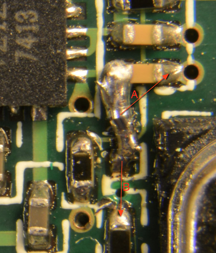
A: 600 Ohm (displays 0.600 with MM setting 2kOhm)
B: 0.06 Ohm (displays 0.06 wit MM setting 200Ohm)
(add the MM setting, cause not 100% shure about the conversion)
Is there a indicator how i can verify if it works?
I tried without the shield in the lowest setting and get a range about 5-10cm.
What range should it be? 1m? 10m?
The last think I would try, is to resolder my short and tried with a isolated wire and only
solder the two ends, to exclude the possibility to short a trace below.
Unter the solder is a thin (not thin enought) copper core of a wire.
I took a MM and messured from my soldered short to another endpoint, so I get shure there are a connection (no cold solder). Right?
I would say, that my messurements told me that there are a connection and it should work. But please correct me.
A: 600 Ohm (displays 0.600 with MM setting 2kOhm)
B: 0.06 Ohm (displays 0.06 wit MM setting 200Ohm)
(add the MM setting, cause not 100% shure about the conversion)
Is there a indicator how i can verify if it works?
I tried without the shield in the lowest setting and get a range about 5-10cm.
What range should it be? 1m? 10m?
The last think I would try, is to resolder my short and tried with a isolated wire and only
solder the two ends, to exclude the possibility to short a trace below.
- aMax
-
- Offline
Less
More
- Posts: 776
13 Feb 2015 11:13 #28627
by aMax
Devo7e, TaranisQ X7, R9M , 4in1 MM, Futaba FC18plusV3.2 & DFT/FLD-02
Replied by aMax on topic Removing shield and diode 7E for better reach
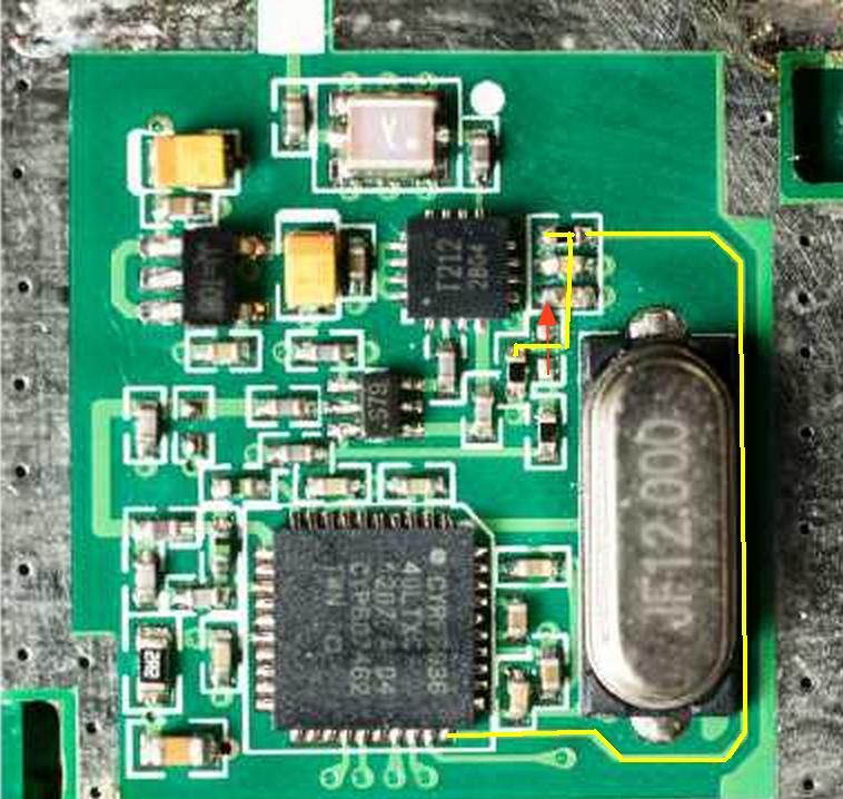
...yellow = new bridge
...blue = measured points = 0 ohms
...blue = measured points = 0 ohms
Attachment not found
Devo7e, TaranisQ X7, R9M , 4in1 MM, Futaba FC18plusV3.2 & DFT/FLD-02
- karl007
-
- Offline
Less
More
- Posts: 9
13 Feb 2015 11:26 #28628
by karl007
Replied by karl007 on topic Removing shield and diode 7E for better reach
thanks aMax for your quick response.
just to make shure i do it right")
just to make shure i do it right
new bridge after remove my old solder?aMax wrote: ...yellow = new bridge
messure points after solder the new bridge, to check if it works?aMax wrote: ...blue = measured points = 0 ohms
- aMax
-
- Offline
Less
More
- Posts: 776
13 Feb 2015 11:42 - 13 Feb 2015 12:17 #28629
by aMax
Devo7e, TaranisQ X7, R9M , 4in1 MM, Futaba FC18plusV3.2 & DFT/FLD-02
Replied by aMax on topic Removing shield and diode 7E for better reach
Please check blue first.... just to know, if there was a short or not.
Yellow is the allowed bridge...., but if you are able, take the bottom pad of the removed diode.
Edit: You only will find one connection with 0 Ohms, I don´t know to which pad the trace goes, but I think to the left.
Added a picture of the PACTL lines.
Yellow is the allowed bridge...., but if you are able, take the bottom pad of the removed diode.
Edit: You only will find one connection with 0 Ohms, I don´t know to which pad the trace goes, but I think to the left.
Added a picture of the PACTL lines.
Devo7e, TaranisQ X7, R9M , 4in1 MM, Futaba FC18plusV3.2 & DFT/FLD-02
Last edit: 13 Feb 2015 12:17 by aMax. Reason: picture added
- karl007
-
- Offline
Less
More
- Posts: 9
13 Feb 2015 17:05 #28635
by karl007
Both pins got 0.6 Ohm.. So there is an unwanted short to the trace below, right?
Replied by karl007 on topic Removing shield and diode 7E for better reach
aMax wrote: Please check blue first.... just to know, if there was a short or not.
Both pins got 0.6 Ohm.. So there is an unwanted short to the trace below, right?
- karl007
-
- Offline
Less
More
- Posts: 9
15 Feb 2015 13:17 #28720
by karl007
Replied by karl007 on topic Removing shield and diode 7E for better reach
Ok, I removed my soldered short and get the same messurements (0.6 Ohm for both blue lines).
So the trace below are OK.
Then I add a wire along your yellow line and now it worked.
Thanks for being so patient and helpfull to me !!
Promise, I never solder smd anymore!
So the trace below are OK.
Then I add a wire along your yellow line and now it worked.
Thanks for being so patient and helpfull to me !!
Promise, I never solder smd anymore!
- aMax
-
- Offline
Less
More
- Posts: 776
15 Feb 2015 14:12 #28723
by aMax
Devo7e, TaranisQ X7, R9M , 4in1 MM, Futaba FC18plusV3.2 & DFT/FLD-02
Replied by aMax on topic Removing shield and diode 7E for better reach
Nice to hear..
What is your result now with range test at 100uW?
What is your result now with range test at 100uW?
Devo7e, TaranisQ X7, R9M , 4in1 MM, Futaba FC18plusV3.2 & DFT/FLD-02
- Jerm357
-
- Offline
Less
More
- Posts: 7
27 May 2015 17:45 #33064
by Jerm357
Replied by Jerm357 on topic Removing shield and diode 7E for better reach
Since so many have done this mod, can someone please tell me if the voltage fluctuating on the LCD screen is normal after its done?
When using the cyrf6936 module, at the lowest power of 100uw, the battery voltage was between 5.10 and 5.12 jumping back and forth. With the full power of 150mw, the voltage fluctuates between like 5.06 and 5.10. The A7105 module is unaffected and is acting the same as it was before the mod. This all make sense and I think is working like it should since Im asking more power from the cyrf6936 module now, but I just want to make sure this is happening to everyone who did the mod.
When using the cyrf6936 module, at the lowest power of 100uw, the battery voltage was between 5.10 and 5.12 jumping back and forth. With the full power of 150mw, the voltage fluctuates between like 5.06 and 5.10. The A7105 module is unaffected and is acting the same as it was before the mod. This all make sense and I think is working like it should since Im asking more power from the cyrf6936 module now, but I just want to make sure this is happening to everyone who did the mod.
- aMax
-
- Offline
Less
More
- Posts: 776
27 May 2015 19:53 - 27 May 2015 20:03 #33069
by aMax
Devo7e, TaranisQ X7, R9M , 4in1 MM, Futaba FC18plusV3.2 & DFT/FLD-02
Replied by aMax on topic Removing shield and diode 7E for better reach
Yes, seem to be normal, max 0.06 V at 100/150mW.
At 100uW up to 30 mW, you will not notice it, no oscillating at my 7e,
The next difference is telemetry on/off at full power.
With Devo little less than with DSMX. Don't know why.......
At 100uW up to 30 mW, you will not notice it, no oscillating at my 7e,
The next difference is telemetry on/off at full power.
With Devo little less than with DSMX. Don't know why.......
Devo7e, TaranisQ X7, R9M , 4in1 MM, Futaba FC18plusV3.2 & DFT/FLD-02
Last edit: 27 May 2015 20:03 by aMax.
- Jerm357
-
- Offline
Less
More
- Posts: 7
27 May 2015 20:42 #33075
by Jerm357
Replied by Jerm357 on topic Removing shield and diode 7E for better reach
Ok, cool. Just to make sure, heres a video of what mines doing at full power. Does your voltage do the same?
- mstrghettorigg
-
- Offline
Less
More
- Posts: 13
31 May 2015 22:34 #33296
by mstrghettorigg
Replied by mstrghettorigg on topic Removing shield and diode 7E for better reach
So I tried this mod and it looks like the 10k resistor is missing. (One in violet on page 2)
I'm pretty sure I didn't remove this and as far as I know it is a new unit.
I can't seem to get the range to increase. I left the diode on and jumpered the two side together.
I changed it to enable by taking the semicolong out of "has_pa-cyrf6936 = 1"
I did not take the semicolon out of "; enable-cyrf6936 = B12" (I tried both ways)
So I'm not sure if it's just the missing 10k that's causing the issue. Has anyone had an unit with missing resistors?
any help would be appreciated.
- PhracturedBlue
-
- Offline
Less
More
- Posts: 4403
31 May 2015 23:58 #33300
by PhracturedBlue
Replied by PhracturedBlue on topic Removing shield and diode 7E for better reach
If you take a picture it may help identify what is going on.
- mstrghettorigg
-
- Offline
Less
More
- Posts: 13
01 Jun 2015 04:04 - 01 Jun 2015 04:09 #33304
by mstrghettorigg
Replied by mstrghettorigg on topic Removing shield and diode 7E for better reach
Thanks for the feedback.
I tried taking it earlier and I couldn't zoom in enough, but i used a loupe and I got it hopefully good enough for you guys to see what's going on.
Please let me know if you have any ideas.
I tried taking it earlier and I couldn't zoom in enough, but i used a loupe and I got it hopefully good enough for you guys to see what's going on.
Please let me know if you have any ideas.
Last edit: 01 Jun 2015 04:09 by mstrghettorigg.
- mstrghettorigg
-
- Offline
Less
More
- Posts: 13
01 Jun 2015 04:09 #33306
by mstrghettorigg
Replied by mstrghettorigg on topic Removing shield and diode 7E for better reach
OK. I must be dumb because I can't figure out how to attach an image...
- PhracturedBlue
-
- Offline
Less
More
- Posts: 4403
01 Jun 2015 04:10 #33307
by PhracturedBlue
Replied by PhracturedBlue on topic Removing shield and diode 7E for better reach
make sure it is no more than 1MB or just attach a link.
- mstrghettorigg
-
- Offline
Less
More
- Posts: 13
01 Jun 2015 04:13 - 01 Jun 2015 04:16 #33308
by mstrghettorigg
Replied by mstrghettorigg on topic Removing shield and diode 7E for better reach
Let's see if this works.
So it's the resistor below the diode I jumped is missing and I believe this is the 10K that was mentioned earlier.
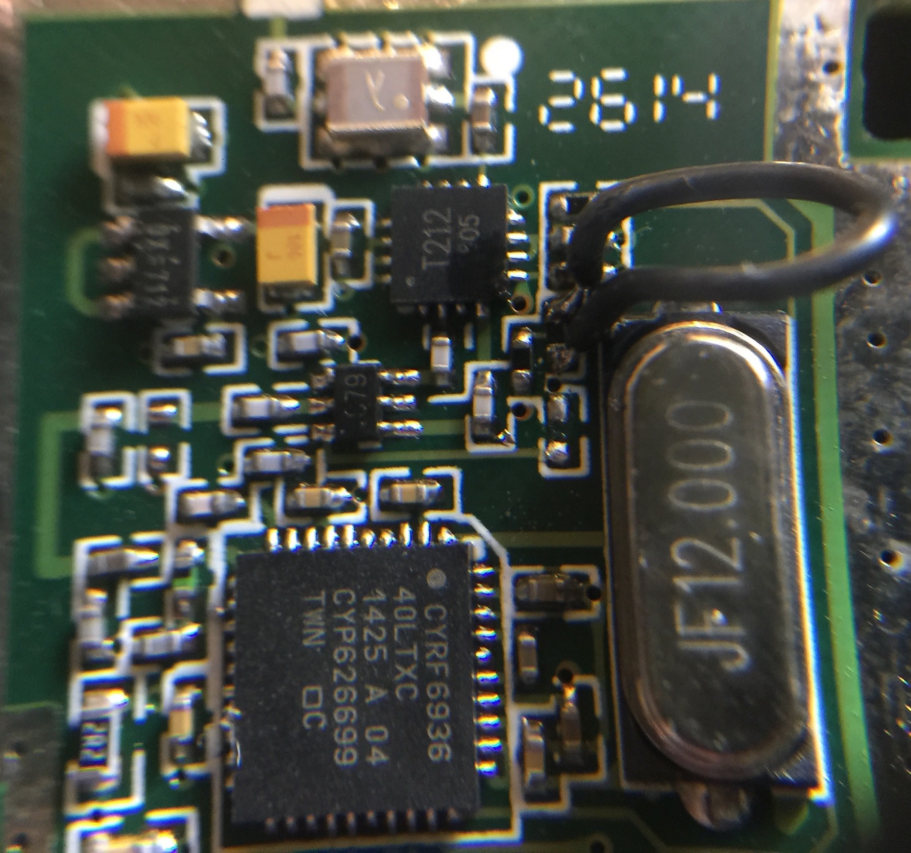
So it's the resistor below the diode I jumped is missing and I believe this is the 10K that was mentioned earlier.
Last edit: 01 Jun 2015 04:16 by mstrghettorigg.
- PhracturedBlue
-
- Offline
Less
More
- Posts: 4403
01 Jun 2015 04:52 #33309
by PhracturedBlue
Replied by PhracturedBlue on topic Removing shield and diode 7E for better reach
What color was the device you removed and replaced with a jumper? was it black, or a yellow/white color? I haven't looked at the internals of a 7e for a couple years, and I don;t remember the circuit layout, so I am unsure what the missing resistor in your image is for. There is an indication that they may have changed the board components recently, and if so , the diode mod may not be the proper solution. I would need to see a 'pre modified' transmitter to assess.
- mstrghettorigg
-
- Offline
Less
More
- Posts: 13
01 Jun 2015 04:58 #33310
by mstrghettorigg
Replied by mstrghettorigg on topic Removing shield and diode 7E for better reach
The part is black and I did not remove them. I just jumped both sides with the wire with the black part intact.
The resistance is reading 0 when I probe both side.
Other than that the image is pre modified. I'm sure it's probably very hard to see anything with that image though.
Please let me know if you have any ideas on what I can try.
The resistance is reading 0 when I probe both side.
Other than that the image is pre modified. I'm sure it's probably very hard to see anything with that image though.
Please let me know if you have any ideas on what I can try.
- aMax
-
- Offline
Less
More
- Posts: 776
01 Jun 2015 12:09 - 01 Jun 2015 12:14 #33314
by aMax
www.deviationtx.com/forum/3-feedback-que...each?start=120#28384
...the reading is 12.2k at both directions.
I messured the removed part.
Edit: Don't care about the yellow square...., the part is right besides.
Devo7e, TaranisQ X7, R9M , 4in1 MM, Futaba FC18plusV3.2 & DFT/FLD-02
Replied by aMax on topic Removing shield and diode 7E for better reach
Have a look at ..PhracturedBlue wrote: What color was the device you removed and replaced with a jumper? may not be the proper solution. I ..........
www.deviationtx.com/forum/3-feedback-que...each?start=120#28384
...the reading is 12.2k at both directions.
I messured the removed part.
Edit: Don't care about the yellow square...., the part is right besides.
Devo7e, TaranisQ X7, R9M , 4in1 MM, Futaba FC18plusV3.2 & DFT/FLD-02
Last edit: 01 Jun 2015 12:14 by aMax.
- mstrghettorigg
-
- Offline
Less
More
- Posts: 13
01 Jun 2015 12:36 #33315
by mstrghettorigg
Replied by mstrghettorigg on topic Removing shield and diode 7E for better reach
Hi aMax,
Are you saying that I need to add a 12.2k ohm resistor at the missing area on my picture?
Please confirm.
Are you saying that I need to add a 12.2k ohm resistor at the missing area on my picture?
Please confirm.
- Forum
- News, Announcements and Feedback
- Feedback & Questions
- Removing shield and diode 7E for better reach
Time to create page: 0.693 seconds
-
Home

-
Forum
-
News, Announcements and Feedback
-
Feedback & Questions
- Removing shield and diode 7E for better reach