
- Posts: 305
- Forum
- News, Announcements and Feedback
- Feedback & Questions
- Removing shield and diode 7E for better reach
Removing shield and diode 7E for better reach
- Arakon
-
- Offline
Less
More
27 Jun 2015 09:42 #34736
by Arakon
Replied by Arakon on topic Removing shield and diode 7E for better reach
I've noticed 25mm antennas on a few chinese receivers for various things.. I think someone got wrong info at some point and everyone now uses it.
- Thomas.Heiss
-
- Offline
Less
More
- Posts: 698
27 Jun 2015 13:50 #34748
by Thomas.Heiss
Replied by Thomas.Heiss on topic Removing shield and diode 7E for better reach
It is clearly stated by HH support that the antenna must not be 25mm but 31,25mm (30-31mm).
Different HF members confirmed that for the 200QX antenna that this is not always the case. Was not for me either.
So it makes no sense to complain about bad signal when the 200QX antenna even does not have the right size lambda 1/4.
Guys, get a real good Spektrum receivers with telemetry (TM) and do your tests with that")
Different HF members confirmed that for the 200QX antenna that this is not always the case. Was not for me either.
So it makes no sense to complain about bad signal when the 200QX antenna even does not have the right size lambda 1/4.
Guys, get a real good Spektrum receivers with telemetry (TM) and do your tests with that
- gdenton
-
- Offline
Less
More
- Posts: 71
11 Jul 2015 02:39 #35321
by gdenton
Replied by gdenton on topic Removing shield and diode 7E for better reach
I received a new 7E today, flashed with latest nightly.
After reading this thread I decided to do a quick test before doing the diode mod.
I enabled the PA in the hardware.ini file.
I then varied the power output settings and it definitely makes a difference.
Using an OrangeRX R615X receiver:
At the lowest setting the transmitter had to be within a couple of feet of the receiver.
At the highest setting I walked out ~500 feet and still had a link but the LED wasn't solid.
Is this the same results that is seen after the diode mod?
Does this mean the PA is enabled from the factory and the diode mod is no longer required?
- robca
-
- Offline
Less
More
- Posts: 174
11 Jul 2015 09:15 #35328
by robca
Replied by robca on topic Removing shield and diode 7E for better reach
It simply means that the Deviation firmware correctly sets power levels in the main chip. The diode disables the power amplifier (PA), and by shorting the diode you enable (in hardware) the PA. Shorting the diode should increase your Tx power significantly.
As a counterproof, try disabling the PA in your INI file, and repeat the test. With the original 7E, you should see no difference between having the PA enabled in INI or not. 500 ft is what an un-modified 7E can do, a modified 7E can do 5000 ft (line of sight). Enabling the PA in the INI file, without the diode mode, makes no difference
As a counterproof, try disabling the PA in your INI file, and repeat the test. With the original 7E, you should see no difference between having the PA enabled in INI or not. 500 ft is what an un-modified 7E can do, a modified 7E can do 5000 ft (line of sight). Enabling the PA in the INI file, without the diode mode, makes no difference
- aMax
-
- Offline
Less
More
- Posts: 776
11 Jul 2015 10:17 #35330
by aMax
Devo7e, TaranisQ X7, R9M , 4in1 MM, Futaba FC18plusV3.2 & DFT/FLD-02
Replied by aMax on topic Removing shield and diode 7E for better reach
Yes, you are right, even on my S603 the antenna was 26mm. Therefore I had to removed a part of the shielding to adjust the length for a quarter wavelenght.Arakon wrote: I've noticed 25mm antennas on a few chinese receivers for various things.. I think someone got wrong info at some point and everyone now uses it.
Devo7e, TaranisQ X7, R9M , 4in1 MM, Futaba FC18plusV3.2 & DFT/FLD-02
- gdenton
-
- Offline
Less
More
- Posts: 71
11 Jul 2015 12:59 #35332
by gdenton
OK - I understand - thanks.
I'll crack it open as soon as I can.
Replied by gdenton on topic Removing shield and diode 7E for better reach
robca wrote: It simply means that the Deviation firmware correctly sets power levels in the main chip. The diode disables the power amplifier (PA), and by shorting the diode you enable (in hardware) the PA. Shorting the diode should increase your Tx power significantly.
As a counterproof, try disabling the PA in your INI file, and repeat the test. With the original 7E, you should see no difference between having the PA enabled in INI or not. 500 ft is what an un-modified 7E can do, a modified 7E can do 5000 ft (line of sight). Enabling the PA in the INI file, without the diode mode, makes no difference
OK - I understand - thanks.
I'll crack it open as soon as I can.
- Devedander
-
- Offline
Less
More
- Posts: 4
28 Nov 2015 16:54 - 28 Nov 2015 17:03 #40469
by Devedander
I spent hours and probably damaged my controller board some trying to fix this voltage fluctuation... is this really normal for just doing the range mod?
This seems odd because if I change protocals it will stop doing this. Even if I switch back to the original protocol (oe I use DSMX so I can switch to DSM2 then back and now voltage is stable however doesn't connect to quad)
Replied by Devedander on topic Removing shield and diode 7E for better reach
Jerm357 wrote: Ok, cool. Just to make sure, heres a video of what mines doing at full power. Does your voltage do the same?
I spent hours and probably damaged my controller board some trying to fix this voltage fluctuation... is this really normal for just doing the range mod?
This seems odd because if I change protocals it will stop doing this. Even if I switch back to the original protocol (oe I use DSMX so I can switch to DSM2 then back and now voltage is stable however doesn't connect to quad)
Last edit: 28 Nov 2015 17:03 by Devedander.
- Devedander
-
- Offline
Less
More
- Posts: 4
29 Nov 2015 17:57 - 29 Nov 2015 18:02 #40482
by Devedander
I am curios about this because due to damaging the trace protectant under where the diode used to be I cannot use a wire to jump the pads due to risk of shorting the trace.
So I am jumping basically exactly the yellow line n this picture (ie my wire goes from the top of the bottom diode to the left leg of the top one)
I am not convinced it's working right as I only get 200 metes or so of range but I am wondering:
1: Is what I did theoretically sound? id if you can't bridge the original diode mount points, can you just bridge the yellow line and get the same result?
2: How does the diode work if it's in line with other diodes? Does the bard read certain resistance and turn off the PA? Because I would think if it was just a matter of reading any resistance then the remaining diode in line would still provide that.
3: Which is leg 5 of the T212? Because if the through hole (basically where the red letter B is in the picture above) really does go to what I think is pin 5, then it also shorts directly to the left pad of the thing marked A as leg 5 seems to be connected by trace to a through hole and the left side of A... I want o test my connections but need to mak sure I am testing the right things....
Thanks!
Replied by Devedander on topic Removing shield and diode 7E for better reach
aMax wrote: ...yellow = new bridge
...blue = measured points = 0 ohms
Attachment not found
I am curios about this because due to damaging the trace protectant under where the diode used to be I cannot use a wire to jump the pads due to risk of shorting the trace.
So I am jumping basically exactly the yellow line n this picture (ie my wire goes from the top of the bottom diode to the left leg of the top one)
I am not convinced it's working right as I only get 200 metes or so of range but I am wondering:
1: Is what I did theoretically sound? id if you can't bridge the original diode mount points, can you just bridge the yellow line and get the same result?
2: How does the diode work if it's in line with other diodes? Does the bard read certain resistance and turn off the PA? Because I would think if it was just a matter of reading any resistance then the remaining diode in line would still provide that.
3: Which is leg 5 of the T212? Because if the through hole (basically where the red letter B is in the picture above) really does go to what I think is pin 5, then it also shorts directly to the left pad of the thing marked A as leg 5 seems to be connected by trace to a through hole and the left side of A... I want o test my connections but need to mak sure I am testing the right things....
Thanks!
Last edit: 29 Nov 2015 18:02 by Devedander.
- aMax
-
- Offline
Less
More
- Posts: 776
29 Nov 2015 22:23 #40489
by aMax
Devo7e, TaranisQ X7, R9M , 4in1 MM, Futaba FC18plusV3.2 & DFT/FLD-02
Replied by aMax on topic Removing shield and diode 7E for better reach
This was only work around, ...pads came off. 
...don't refer to this.
...don't refer to this.
Devo7e, TaranisQ X7, R9M , 4in1 MM, Futaba FC18plusV3.2 & DFT/FLD-02
- aMax
-
- Offline
Less
More
- Posts: 776
29 Nov 2015 22:56 - 29 Nov 2015 22:59 #40492
by aMax
en.wikipedia.org/wiki/Velocity_factor
www.rcgroups.com/forums/showthread.php?t=2371720
Devo7e, TaranisQ X7, R9M , 4in1 MM, Futaba FC18plusV3.2 & DFT/FLD-02
Replied by aMax on topic Removing shield and diode 7E for better reach
.... and I was wrong with this. Finally I had to cut the activ part down again,.... to nearly 27mm, because of the velocity factor at my coax.aMax wrote:
Yes, you are right, even on my S603 the antenna was 26mm. Therefore I had to removed a part of the shielding to adjust the length for a quarter wavelenght.Arakon wrote: I've noticed 25mm antennas on a few chinese receivers for various things.. I think someone got wrong info at some point and everyone now uses it.
en.wikipedia.org/wiki/Velocity_factor
www.rcgroups.com/forums/showthread.php?t=2371720
Devo7e, TaranisQ X7, R9M , 4in1 MM, Futaba FC18plusV3.2 & DFT/FLD-02
Last edit: 29 Nov 2015 22:59 by aMax.
- Devedander
-
- Offline
Less
More
- Posts: 4
30 Nov 2015 03:08 #40494
by Devedander
Replied by Devedander on topic Removing shield and diode 7E for better reach
My situation requires a workaround because I exposed the traces under the diode so bridging it now has a huge chance of shorting it against the exposed trace.
I am pretty sure I did that the other night resulting in a 1 meter range.
So for now while I prefer not to do it that way, I just need to confirm it should indeed work? Based on checking resistance everywhere I can think to it seems it should as I get no resistance between the solder pads and their adjoining chips along the same trace...
I have a conductive pen coming in the mail, I will probably try o repair the damaged trace and bridge the original pads in a slight detour but that won't be easy so just trying to verify all my options before I screw up even more
- aMax
-
- Offline
Less
More
- Posts: 776
30 Nov 2015 09:43 - 30 Nov 2015 09:50 #40500
by aMax
Devo7e, TaranisQ X7, R9M , 4in1 MM, Futaba FC18plusV3.2 & DFT/FLD-02
Replied by aMax on topic Removing shield and diode 7E for better reach
It would have been more useful you had posted a photo of your module.... 
Here is a picture of how the pactl traces( yellow) run. The red arrows could be your bridge to get around your problem
If you need more space, you can even use the via below as one solder point, but be very careful !!
Here is a picture of how the pactl traces( yellow) run. The red arrows could be your bridge to get around your problem
If you need more space, you can even use the via below as one solder point, but be very careful !!
Devo7e, TaranisQ X7, R9M , 4in1 MM, Futaba FC18plusV3.2 & DFT/FLD-02
Last edit: 30 Nov 2015 09:50 by aMax.
- Devedander
-
- Offline
Less
More
- Posts: 4
30 Nov 2015 19:21 - 30 Nov 2015 19:24 #40509
by Devedander
Replied by Devedander on topic Removing shield and diode 7E for better reach
Sorry here's the best picture I could get.
Good thing I did take the pic because it isn't exactly what I remember doing (at 5:30 am on a very stressed out night).
Ignore the small flyaway wire at the top, it is above everything, doesn't contact anything and I have measured resistance against it. It is also covered by electrical tape when it's all put back together so it's not shorting to the shield either.
Your picture is clearer so what I did is draw some purple lines to show where I tested resistance to make sure they are not shorted. Both purple lines represent resistance of 1.
Where your red arrow is I show near zero resistance which is in line with the resistance I get when touching the probes together directly.
So I think all should be good... but my range maxes out at 1000 feet and in real life conditions is only reliable up to about 200 meters before there is significant chance of dropouts.
This is with PA enabled in hardware and power pushed to 150mw.
In Devioation 4.01 I can hear the speaker interference ramp up at each step in power including 100-150mw but I am not sure that means the PAi is actually working.
My voltage meter also constantly jumps around by sever hundreths of a volt all the time.
Thanks for any input!
Last edit: 30 Nov 2015 19:24 by Devedander.
- mzbeg
-
- Offline
Less
More
- Posts: 44
01 Dec 2015 23:43 #40543
by mzbeg
In the above under the 7e Pin Point, Point 3 is MOSI and Point 4 is MISO, but go to bitbucket.org/PhracturedBlue/deviation/wiki/Devo7eModuleInstall the points are other way around.
I am a new to all this, I might be wrong. I just want to know which is correct or my eyes are playing tricks with me .
Replied by mzbeg on topic Removing shield and diode 7E for better reach
MicSmitty wrote: Welp, wish I didn't attempt to do this mod with a regular soldering iron either as I also failed
So I purchased a 8s module and it's on the way. However I have some questions:
Since the 8s module sits ontop of the 7e's PCB and the pinouts don't line up perfectly, how do you install it? Use wires and secure 8s module somewhere else?
To help others in installing a 8s module in a 7e transmitter (and so others understand what I'm asking) below in the attachment pic is the pinout I found in another thread by PB. I just wrote it differently to show how you can't place the 8s module directly on the 7e PCB like it was...
Also, what happens to the 8s module pinouts 7,8, and 9? Don't use them?
Again, thanks to all for this project/forum/user materials.
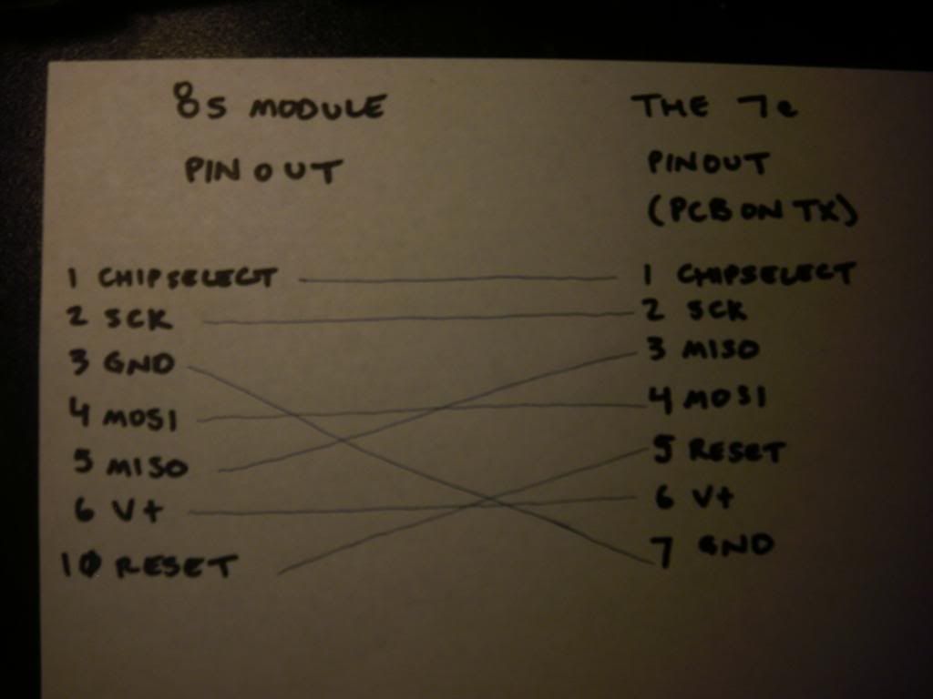

In the above under the 7e Pin Point, Point 3 is MOSI and Point 4 is MISO, but go to bitbucket.org/PhracturedBlue/deviation/wiki/Devo7eModuleInstall the points are other way around.
I am a new to all this, I might be wrong. I just want to know which is correct or my eyes are playing tricks with me .
- Thor368
-
- Offline
Less
More
- Posts: 1
14 Dec 2015 18:38 #40925
by Thor368
Replied by Thor368 on topic Removing shield and diode 7E for better reach
By the way. I heard this mix-up to often now. The 0603 chip that is removed as part of the mod is actually not a diode but a 10k resistor. I did not invest enough time to figure out which exact PA and schematic they are using there but this is quit possibly a input to the PA.
- goodwrench
-
- Offline
Less
More
- Posts: 9
11 Feb 2016 00:23 - 11 Feb 2016 00:25 #42971
by goodwrench
Replied by goodwrench on topic Removing shield and diode 7E for better reach
aMax wrote: Please check blue first.... just to know, if there was a short or not.
Yellow is the allowed bridge...., but if you are able, take the bottom pad of the removed diode.
Edit: You only will find one connection with 0 Ohms, I don´t know to which pad the trace goes, but I think to the left.
Added a picture of the PACTL lines.
Hi. Can I please get some help with this? I tried the diode mod and torn the upper solder pad off. I found this in an earlier post, but I don't quite understand where to install the new bridge. Is it where the red arrow is or do I run wires the same as the yellow lines? See attached picture
Last edit: 11 Feb 2016 00:25 by goodwrench.
- rasqba
-
- Offline
Less
More
- Posts: 24
16 Feb 2016 23:30 #43192
by rasqba
Replied by rasqba on topic Removing shield and diode 7E for better reach
Hi,
what is the best way to check if the mod was succesful, considering I didn't do a range test before the mod, nor current measurement.
What is average range on the lowest setting with and without the mod? Or maybe there is a better way to make sure the mod was succesful?
what is the best way to check if the mod was succesful, considering I didn't do a range test before the mod, nor current measurement.
What is average range on the lowest setting with and without the mod? Or maybe there is a better way to make sure the mod was succesful?
- RumbleBeeAL
-
- Offline
Less
More
- Posts: 18
04 Mar 2016 12:00 - 22 Mar 2017 20:50 #44094
by RumbleBeeAL
Replied by RumbleBeeAL on topic Removing shield and diode 7E for better reach
The component being removed for this mod is NOT a diode.
It is however a 10k Ohm resistor.
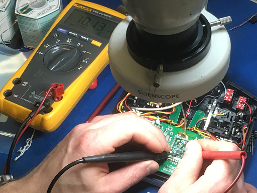
The photo above is with the component removed from circuit and being measured while resting on the larger component.
Note, I reinstalled the resistor and simply solder bridged over the top of it so that I can reverse the mod if later desired.
It is however a 10k Ohm resistor.
The photo above is with the component removed from circuit and being measured while resting on the larger component.
Note, I reinstalled the resistor and simply solder bridged over the top of it so that I can reverse the mod if later desired.
Last edit: 22 Mar 2017 20:50 by RumbleBeeAL. Reason: Add more detail.
- RumbleBeeAL
-
- Offline
Less
More
- Posts: 18
05 Mar 2016 05:27 #44130
by RumbleBeeAL
Replied by RumbleBeeAL on topic Removing shield and diode 7E for better reach
noob disclaimer: My fingers are crossed for the images to upload -
Tonight, I used a Spectrum Analyzer to help validate the differences in output power when changed via software settings under
--> Model menu --> Model setup --> Tx power
100uW
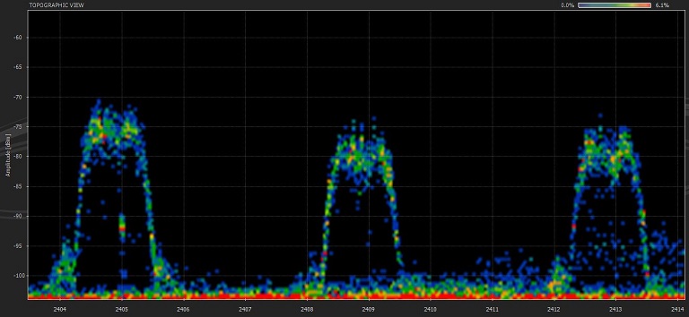
300uW
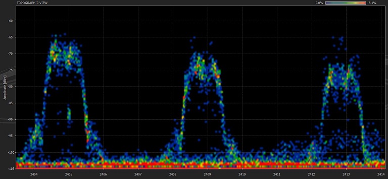
1mW
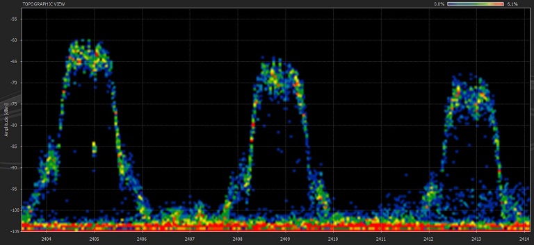
3mW
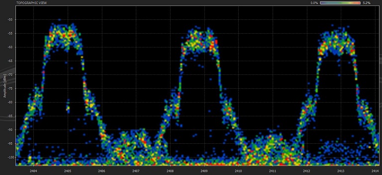
10mW
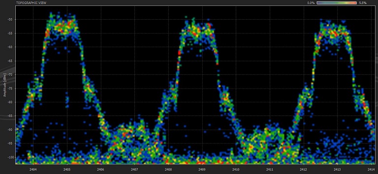
30mW
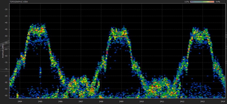
100mW
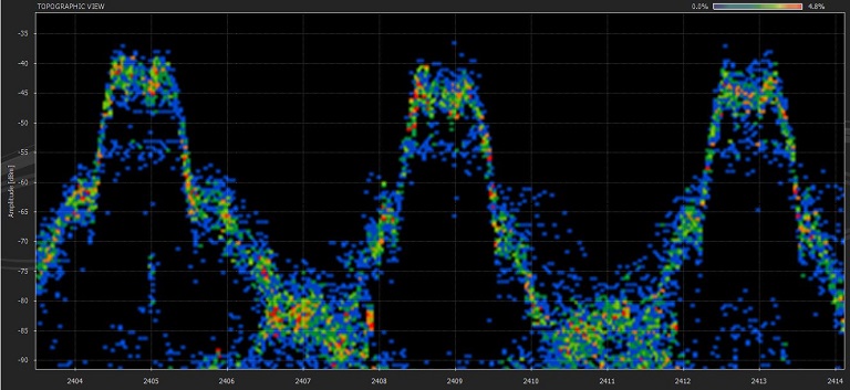
150mW[/b]
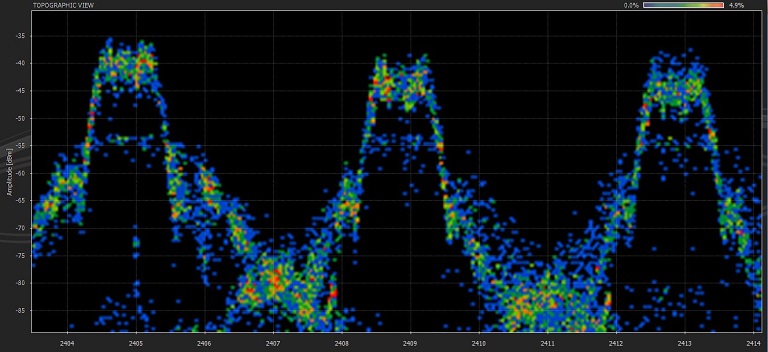
Scan Settings:
Start: 2401.000MHz
Stop: 2416.234
Step Size: 25.391KHz
Sweep: 1.71 Sec.
Res BW: 58.036 KHz
Setup: Unit Under Test #1 (Modded Devo 7E) was 2ft from Analyzer's Rx Antenna
Note, I did not test before performing the hardware mod by bypassing the 10k Ohm resistor (more commonly being referred to as diode) followed by editing the hardware.ini file within the root folder. However, I plan to measure a stock Devo 7E before mods are performed under similar test conditions.
I also plan to perform similar testing at distance in open field as time permits.
Tonight, I used a Spectrum Analyzer to help validate the differences in output power when changed via software settings under
--> Model menu --> Model setup --> Tx power
100uW
300uW
1mW
3mW
10mW
30mW
100mW
150mW[/b]
Scan Settings:
Start: 2401.000MHz
Stop: 2416.234
Step Size: 25.391KHz
Sweep: 1.71 Sec.
Res BW: 58.036 KHz
Setup: Unit Under Test #1 (Modded Devo 7E) was 2ft from Analyzer's Rx Antenna
Note, I did not test before performing the hardware mod by bypassing the 10k Ohm resistor (more commonly being referred to as diode) followed by editing the hardware.ini file within the root folder. However, I plan to measure a stock Devo 7E before mods are performed under similar test conditions.
I also plan to perform similar testing at distance in open field as time permits.
- aMax
-
- Offline
Less
More
- Posts: 776
05 Mar 2016 11:47 - 05 Mar 2016 15:11 #44138
by aMax
Devo7e, TaranisQ X7, R9M , 4in1 MM, Futaba FC18plusV3.2 & DFT/FLD-02
Replied by aMax on topic Removing shield and diode 7E for better reach
Well done.
I missed something like this since long. The last step to 150 mW seems to provide you not only little more power
but also more interference.
I missed something like this since long. The last step to 150 mW seems to provide you not only little more power
but also more interference.
Devo7e, TaranisQ X7, R9M , 4in1 MM, Futaba FC18plusV3.2 & DFT/FLD-02
Last edit: 05 Mar 2016 15:11 by aMax. Reason: ..grammar..:-(
- Forum
- News, Announcements and Feedback
- Feedback & Questions
- Removing shield and diode 7E for better reach
Time to create page: 0.380 seconds
-
Home

-
Forum
-
News, Announcements and Feedback
-
Feedback & Questions
- Removing shield and diode 7E for better reach