
- Posts: 3
- Forum
- News, Announcements and Feedback
- Feedback & Questions
- Removing shield and diode 7E for better reach
Removing shield and diode 7E for better reach
- Miscelaneo
-
- Offline
Less
More
31 Aug 2016 08:58 - 31 Aug 2016 15:47 #53320
by Miscelaneo
Replied by Miscelaneo on topic Removing shield and diode 7E for better reach
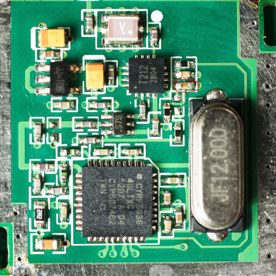
Does any one knows the value of this capacitator, resistor or what ever is It?  I blown mine away
I got it worse and tried this:
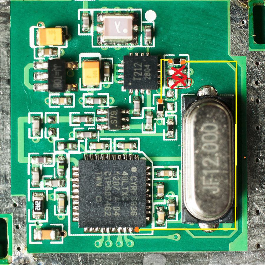
Wont work.
I got it worse and tried this:
Wont work.
Last edit: 31 Aug 2016 15:47 by Miscelaneo.
- ketsa
-
- Offline
Less
More
- Posts: 47
02 Sep 2016 20:15 #53423
by ketsa
Replied by ketsa on topic Removing shield and diode 7E for better reach
Reminder : there is no need to remove the component.
Just bridge on top of it : a lot less risky.
Just bridge on top of it : a lot less risky.
- Kahless
-
- Offline
Less
More
- Posts: 2
05 Sep 2016 14:19 #53514
by Kahless
Replied by Kahless on topic Removing shield and diode 7E for better reach
Could the diode be shorted by using a carbon graphite pencil to draw a conductive bridge? Ive read about people on a flashlight forum using this method to turn their multimode flash lights to single mode by shorting a smd capacitor in this way.
- CesiumSalami
-
- Offline
Less
More
- Posts: 51
30 Oct 2016 17:56 - 30 Oct 2016 18:07 #55527
by CesiumSalami
Replied by CesiumSalami on topic Removing shield and diode 7E for better reach
Oy - I didn't really grasp just how small all these items were until I cracked the 7e open. Much smaller than I thought. Included a 3.5mm headphone jack for reference. Notice the diode is about the size of the top point of the headphone jack .... I'm pretty new at soldering so this was a test of my abilities for sure. I just cut a wire - tinned it and delicately balanced it ontop and touched the soldering iron to the top quickly. I think I got it on the first shot - but then, of course, thought I could revise it better and spent 20 minutes trying to balance it again.
Also used some kapton tape help prevent me from nuking some of the other electronics - was definitely helpful! There is a wire under the blob of solder...
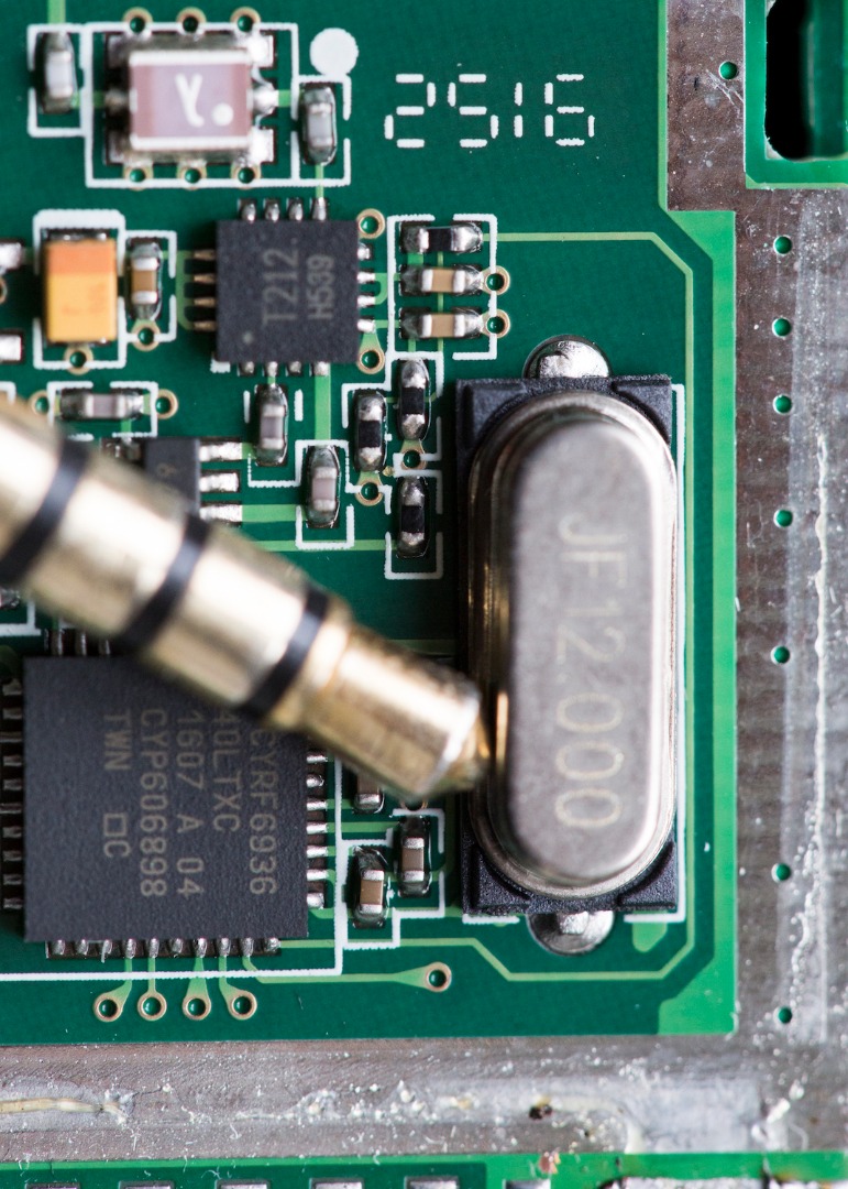
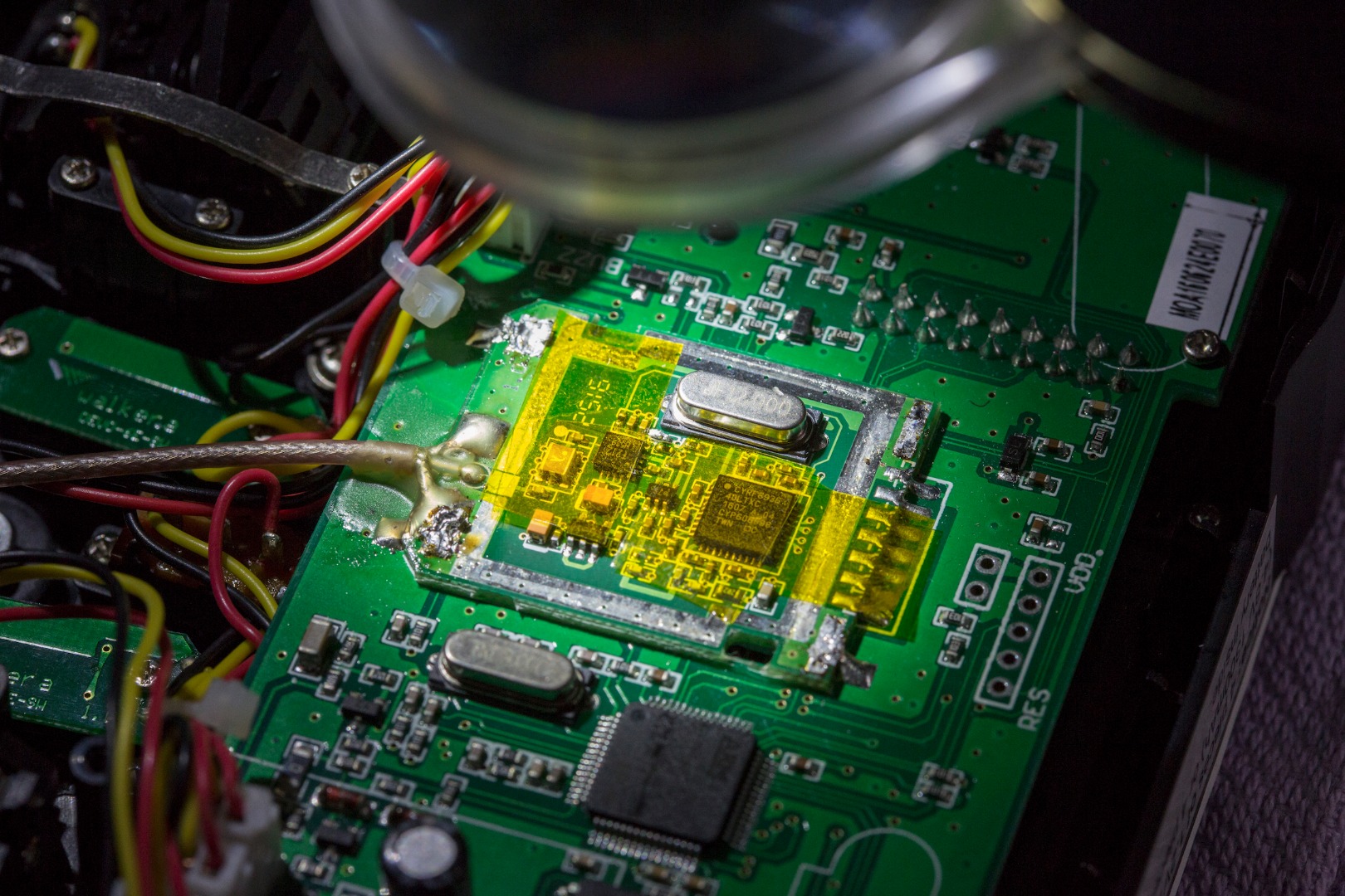
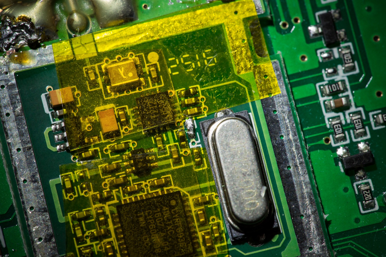
Also used some kapton tape help prevent me from nuking some of the other electronics - was definitely helpful! There is a wire under the blob of solder...
Last edit: 30 Oct 2016 18:07 by CesiumSalami.
- Land Sick Sailor
-
- Offline
Less
More
- Posts: 1
03 Dec 2016 14:49 - 03 Dec 2016 14:50 #56481
by Land Sick Sailor
Replied by Land Sick Sailor on topic Forget Removing shield and diode 7E?
While we can leave the diode and just short it, this made me look at the HD picture above.
I notice a PTH (Plated Through Hole - a hole which runs from one side to the other that older parts were inserted into and soldered, now just used for connecting between layers to get to the next part).
One PTH seems to be below the diode pad, and another seems to be connected after the Cap pad beside the T212.
Can someone check on the other side of the board and see if one can gain access, if so just run a wire from one PTH to the other and solder them in each hole?
I cant check as dont have a DEVO, but from the picture seems fine.
Last edit: 03 Dec 2016 14:50 by Land Sick Sailor. Reason: mistake
- aMax
-
- Offline
Less
More
- Posts: 776
03 Dec 2016 16:13 #56483
by aMax
Devo7e, TaranisQ X7, R9M , 4in1 MM, Futaba FC18plusV3.2 & DFT/FLD-02
Replied by aMax on topic Forget Removing shield and diode 7E?
Just run a wire from via to the first cap.
Devo7e, TaranisQ X7, R9M , 4in1 MM, Futaba FC18plusV3.2 & DFT/FLD-02
- HappyHarry
-
- Offline
Less
More
- Posts: 1136
03 Dec 2016 16:57 #56485
by HappyHarry
i don't think would reduce the resistance enough bud, just use silver windscreen repair paint if you don't want to tackle the soldering
Qapla'")
Replied by HappyHarry on topic Removing shield and diode 7E for better reach
Kahless wrote: Could the diode be shorted by using a carbon graphite pencil to draw a conductive bridge? Ive read about people on a flashlight forum using this method to turn their multimode flash lights to single mode by shorting a smd capacitor in this way.
i don't think would reduce the resistance enough bud, just use silver windscreen repair paint if you don't want to tackle the soldering
Qapla'
- Sero
-
- Offline
- RC-addicted
Less
More
- Posts: 106
03 Dec 2016 20:32 #56494
by Sero
A day without flying can't be called a day.
Replied by Sero on topic Removing shield and diode 7E for better reach
I did a similar mod on a Blade Inductrix (to remove the LVC) with conductive ink, and it works perfect.
A day without flying can't be called a day.
- CesiumSalami
-
- Offline
Less
More
- Posts: 51
04 Dec 2016 01:44 - 04 Dec 2016 01:46 #56500
by CesiumSalami
Replied by CesiumSalami on topic Forget Removing shield and diode 7E?
Just in case you're still interested, here's a photo of the back of the original module. I just pulled it today whilst installing the 4-in-1. Holy moly - the diode mod was a walk in the park compared to installing the 4-in-1 (i thought).
As you can see I almost botched the whole thing by ripping a portion of the contacts off - I don't know how people get this thing off ... it was a bear for me.
That being said, almost the entire back of the module is covered by another PCB - only a sliver shows through to the other side...
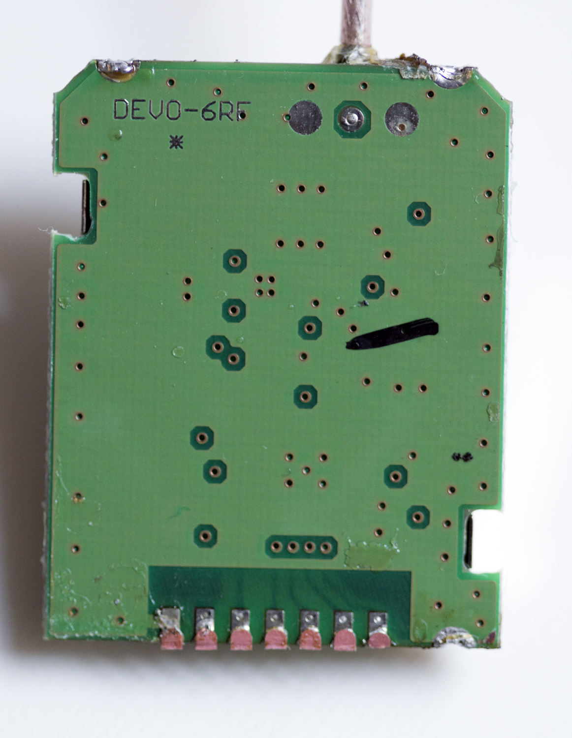
As you can see I almost botched the whole thing by ripping a portion of the contacts off
That being said, almost the entire back of the module is covered by another PCB - only a sliver shows through to the other side...
Last edit: 04 Dec 2016 01:46 by CesiumSalami.
- Peaceliker
-
- Offline
Less
More
- Posts: 8
04 Feb 2017 17:16 #58748
by Peaceliker
Replied by Peaceliker on topic Forget Removing shield and diode 7E?
Hi guys!
After a range mode (i have one 7e with diode mod and one with devo 8s modeul) i hato change in the hw.ini only the has_pa-cyrf6936 = 0 to 1 or have uncomment the enable-cyrf6936 = B12 line too?
Thanks
After a range mode (i have one 7e with diode mod and one with devo 8s modeul) i hato change in the hw.ini only the has_pa-cyrf6936 = 0 to 1 or have uncomment the enable-cyrf6936 = B12 line too?
Thanks
- hengthanak
-
- Offline
Less
More
- Posts: 3
22 Mar 2017 19:14 #60558
by hengthanak
Replied by hengthanak on topic Removing shield and diode 7E for better reach
NEED HELP!!!!
Hi guys! while removing the diode, i accidentally pull one of the pad off. Now i am missing the diode but without the two pad bridge. Am i screw or can i do sth eles? will this effect the range in any way? worst or better than stock? Haven't test mine yet since i haven't receive a receiver yet.
Hi guys! while removing the diode, i accidentally pull one of the pad off. Now i am missing the diode but without the two pad bridge. Am i screw or can i do sth eles? will this effect the range in any way? worst or better than stock? Haven't test mine yet since i haven't receive a receiver yet.
- RumbleBeeAL
-
- Offline
Less
More
- Posts: 18
22 Mar 2017 20:41 - 22 Mar 2017 20:49 #60572
by RumbleBeeAL
Can you attach a photo of the damaged area so that we can determine what "pad" you lifted?
Without a photo, my advice is to try to follow the trace(s) leading form the pad and attach a wire there to achieve the previous goal. If I am correct in assuming what pad you lifted, you need to follow the advice above as the idea is to short (bridge) the two pads together. if you lifted the pad, this may have a negative affect on the intended result of increasing power output.
BTW - Based on my evaluation of the component you are referring to, I believe it is actually a resistor in reality as it has those properties when removed and tested.
Component Type Diode or Resistor? <--Click here!
Replied by RumbleBeeAL on topic Removing shield and diode 7E for better reach
hengthanak wrote: NEED HELP!!!!
Hi guys! while removing the diode, i accidentally pull one of the pad off. Now i am missing the diode but without the two pad bridge. Am i screw or can i do sth eles? will this effect the range in any way? worst or better than stock? Haven't test mine yet since i haven't receive a receiver yet.
Can you attach a photo of the damaged area so that we can determine what "pad" you lifted?
Without a photo, my advice is to try to follow the trace(s) leading form the pad and attach a wire there to achieve the previous goal. If I am correct in assuming what pad you lifted, you need to follow the advice above as the idea is to short (bridge) the two pads together. if you lifted the pad, this may have a negative affect on the intended result of increasing power output.
BTW - Based on my evaluation of the component you are referring to, I believe it is actually a resistor in reality as it has those properties when removed and tested.
Component Type Diode or Resistor? <--Click here!
Last edit: 22 Mar 2017 20:49 by RumbleBeeAL.
- hengthanak
-
- Offline
Less
More
- Posts: 3
23 Mar 2017 01:00 #60584
by hengthanak
Replied by hengthanak on topic Removing shield and diode 7E for better reach
It is a resistor. I have lifted off the pad (circle in blue) (the one that have a resistor before. Can i solder a piece of wiere bettween the two blue dot as i have draw in the picture as the trace seem to be connected from the lifted pad to it.
- hengthanak
-
- Offline
Less
More
- Posts: 3
23 Mar 2017 08:47 #60588
by hengthanak
Replied by hengthanak on topic Removing shield and diode 7E for better reach
Hi guys! NEED HELP
I fup again, lift off both off the p
 ad of the resistor. Now i solder a piece off wire across the two resister as shown in the attachment. Will this work? or do i need to buy the walkera devo s module? Please help im a noob.
I fup again, lift off both off the p
- ketsa
-
- Offline
Less
More
- Posts: 47
25 Mar 2017 07:05 #60713
by ketsa
Replied by ketsa on topic Removing shield and diode 7E for better reach
This is why you should bridge on top of that resistor and not remove it.
- compman2
-
- Offline
Less
More
- Posts: 65
11 Apr 2017 15:10 #61379
by compman2
computer nerd, hobby collector, proud father
Replied by compman2 on topic Removing shield and diode 7E for better reach
I have a 7e module that I have done the range mod on that I am selling. I removed it from my 7e when I added a 4 in 1 module. Check the marketplace.
The range mod is very tedious. I have done two one by removing the diode and placing a jumper. The second by using conductive paint on the top of the diode. The conductive paint is far easier and works just as well.
The range mod is very tedious. I have done two one by removing the diode and placing a jumper. The second by using conductive paint on the top of the diode. The conductive paint is far easier and works just as well.
computer nerd, hobby collector, proud father
- FriedSky
-
- Offline
Less
More
- Posts: 15
25 Apr 2017 20:14 #61775
by FriedSky
Replied by FriedSky on topic Removing shield and diode 7E for better reach
Hi All.
The often referred to diode is actually a 10K resistor on my board.
If you make comparisons between the DEVO6-RF module used in the 7e and the WK-21201RF module, then the 10k resistor is replaced by 2 * 200ohm in parallel ... 100 ohm.
Now why that should affect the T212 PA / LNA maybe down to the different threshold voltages for the swpa swtx inputs.
Anyone care to explain this ?
- rjmcewen63
-
- Offline
- I know how to fly, I'm learning not to crash...
Less
More
- Posts: 21
07 May 2017 05:13 #62086
by rjmcewen63
_
/_/ _ _
/ \/_/_\_\
This email address is being protected from spambots. You need JavaScript enabled to view it.
Replied by rjmcewen63 on topic Removing shield and diode 7E for better reach
Try one of these.
www.amazon.com/MG-Chemicals-Nickel-Condu...rds=trace+repair+pen
www.amazon.com/MG-Chemicals-Nickel-Condu...rds=trace+repair+pen
_
/_/ _ _
/ \/_/_\_\
This email address is being protected from spambots. You need JavaScript enabled to view it.
- Fernandez
-
- Offline
Less
More
- Posts: 983
07 May 2017 08:55 #62091
by Fernandez
Replied by Fernandez on topic Removing shield and diode 7E for better reach
Easiest for me take a piece of servo wires strip a cm or so, then cut away most of the strings from the end, leave a small bundle 4-5 copper or so. Tin the ends with soldering iron. Then bend the wires with a pliers 90 degree, 2mm or so, basically the with of the smd resistor to short.
Now hold the servo wire in place by hand solder it on top of the smd resistor to short it. Then cut away the sticking out servo wire with sidecutter.
Now hold the servo wire in place by hand solder it on top of the smd resistor to short it. Then cut away the sticking out servo wire with sidecutter.
- Forum
- News, Announcements and Feedback
- Feedback & Questions
- Removing shield and diode 7E for better reach
Time to create page: 0.342 seconds
-
Home

-
Forum
-
News, Announcements and Feedback
-
Feedback & Questions
- Removing shield and diode 7E for better reach