
- Posts: 4403
Ultimate7e tutorial: Processor upgrade
- PhracturedBlue
-
- Offline
Less
More
29 Apr 2016 03:06 #47400
by PhracturedBlue
Replied by PhracturedBlue on topic Ultimate7e tutorial: Processor upgrade
the process sounds fine, and it sounds like you have the chip properly programmed. you are sure you are installing at 0x08000000? haven't used the stlink for a long time, but it is possible to step through execution at a specific address, and it should be clear pretty quicly whether the code is in the bootloader or not (PC address should stay < 0x08003000). I haven't done this for a long time, and am describing this from memory.
- silpstream
-
Topic Author
- Offline
Less
More
- Posts: 244
29 Apr 2016 08:42 #47407
by silpstream
Replied by silpstream on topic Ultimate7e tutorial: Processor upgrade
Check all your solder joints with a magnifying glass. Not just for bridges but also for good solder on each pin. When using hot air and paste, I've had situations where a pin didn't get soldered properly.
To step through the address space, I believe it's in the "MCU Core" item under "Target". Can't quite remember and I'm not at home now to check.
To step through the address space, I believe it's in the "MCU Core" item under "Target". Can't quite remember and I'm not at home now to check.
- PhracturedBlue
-
- Offline
Less
More
- Posts: 4403
29 Apr 2016 12:42 #47417
by PhracturedBlue
Replied by PhracturedBlue on topic Ultimate7e tutorial: Processor upgrade
I'm skeptical of bad solder joints, since the only one you need for the bootloader are the usb pins and power and ground (and you already know power & ground are ok, or you couldn't program). The MCU should automatically go into programming mode as soon as it doesn't see any loaded firmware. But definietly sheck the 2 traces that go to the USB port.
- silpstream
-
- Offline
Less
More
- Posts: 244
29 Apr 2016 13:01 #47418
by silpstream
Replied by silpstream on topic Ultimate7e tutorial: Processor upgrade
Wasn't actually worried about the pins needed for programming cause we know that works. But beyond those and the USB, we would want to look at the LCD pins. Potentially also any others that the walkera bootloader might check for (if any like the power control pins). I'm not too familiar with the bootloader, but if everything is starting at 0x08000000 like PB said, then eliminating hardware issues will help.
Another check to do is the vreg. Make sure you are getting 3v3. The vreg and electrolytic cspacitors are pretty close to the processor. Could have taken some damage in the replacement. You won't be able to tell when using st-link if your programmer provides power during programming.
")
Another check to do is the vreg. Make sure you are getting 3v3. The vreg and electrolytic cspacitors are pretty close to the processor. Could have taken some damage in the replacement. You won't be able to tell when using st-link if your programmer provides power during programming.
- PhracturedBlue
-
- Offline
Less
More
- Posts: 4403
29 Apr 2016 15:10 #47420
by PhracturedBlue
Replied by PhracturedBlue on topic Ultimate7e tutorial: Processor upgrade
usb will turn on even if the lcd does not. but yes, you could try driectly connecting 3.3V to the debug header and see if that helps.
- HappyHarry
-
- Offline
Less
More
- Posts: 1136
29 Apr 2016 15:24 #47421
by HappyHarry
Replied by HappyHarry on topic Ultimate7e tutorial: Processor upgrade
thanks for the pointers guys, I'll have a looke again this evening.
is there any chance I buggered something up when I progranmed the chip without boot being jumped? also how did that happen if you need to short boot to flash?
is there any chance I buggered something up when I progranmed the chip without boot being jumped? also how did that happen if you need to short boot to flash?
- PhracturedBlue
-
- Offline
Less
More
- Posts: 4403
29 Apr 2016 15:27 #47422
by PhracturedBlue
Replied by PhracturedBlue on topic Ultimate7e tutorial: Processor upgrade
Damaging the chip is very unlikely if you can program it. However, if it programmed without the boot jumper, I would check for a short on the boot pin.
- HappyHarry
-
- Offline
Less
More
- Posts: 1136
29 Apr 2016 20:09 #47443
by HappyHarry
Replied by HappyHarry on topic Ultimate7e tutorial: Processor upgrade
ok I double checked the soldering and there are no shorts that I can see, and the chip is definitely flashed properly, the 3.3v reg doesn't come on woth the power button, but when I jump the power pins it gives out a steady 3.3v. I tried pulling the battery and hooking 3.3v direct to the debug port gnd and + and that makes no difference, also there is good connectivity between the relevant pins on the mcu and the usb port.
when I go into the stm menu and choose core it opens a window with a load of little boxes with hex addresses, this is way beyond my current knowledge so i'm trying to read up on what it all means, any pointers what I should be looking for there?
this was the chips I purchased, are they the correct ones? >> m.ebay.co.uk/itm/2PCS-MCU-ARM-IC-LQFP-64...?txnId=1630237728017
so with all that it mind is there anything else to check? or do I give up and bin my ever faithfull 7e :/
- silpstream
-
- Offline
Less
More
- Posts: 244
29 Apr 2016 20:42 #47451
by silpstream
Replied by silpstream on topic Ultimate7e tutorial: Processor upgrade
I believe PB is right that you have a short on your boot0 pin to vcc. I tried shorting boot0 to vcc on my 7e and the power switch won't turn things on, but the power jumper does and it drops straight to stm's built in uart bootloader. When it is in this bootloader, you will not see anything light up on the lcd.
Use a multimeter to check the two boot0 jumper pins above the programming header. You'll probably find that it is shorted. Try tracing that cause it might not necessarily be a short at the processor pins. If your 7e was modded before, you could have wires connected that is causing the short. Take some clear close up pics and maybe we can see more.
You can also use a multimeter and probe the boot0 pin (pin 60) to the few adjacent pins next to it for shorts. Vss is only 3 pin away (pin63) and the short could be under the processor pins if you had too much solder paste.
You should be on the right track so don't give up!
- HappyHarry
-
- Offline
Less
More
- Posts: 1136
29 Apr 2016 22:08 #47457
by HappyHarry
Replied by HappyHarry on topic Ultimate7e tutorial: Processor upgrade
nope no short across boot0 (now at least, i probably cleared it when troubleshooting earlier as i fluxed and wicked all 4 sides again etc before i posted here asking for help) and i'm about ready to give up on the poor thing 
one question, when in the stlink software and you open target>mcu core, should you be able to run the code? also to get dfuse to see the tx is there any special method other than the usual deviation method?
time to talk to the other 2 guys as it's bad enough having to buy myself another 7e, i'm not having to be buying them one each too lol
- victzh
-
- Offline
Less
More
- Posts: 1386
29 Apr 2016 22:46 #47460
by victzh
Replied by victzh on topic Ultimate7e tutorial: Processor upgrade
As far as I understand - as soon as target is acquired by ST-Link software it stops running the code. To run the code while connected you need to connect from debugger, not from programmer (which ST-Link software is). No other method except usual Devo's method exist - to "see" the TX from DfuSe it should expose DFU device over the USB. For this bootloader should take control and for this it needs to see EXT button pressed.
How did you find that your boot0 is not pulled up to Vcc? By visual inspection or by using meter?
How did you find that your boot0 is not pulled up to Vcc? By visual inspection or by using meter?
- HappyHarry
-
- Offline
Less
More
- Posts: 1136
29 Apr 2016 23:31 - 29 Apr 2016 23:47 #47461
by HappyHarry
Replied by HappyHarry on topic Ultimate7e tutorial: Processor upgrade
thanks for the info victor, as for boot0 i checked with a meter for continuity, both between the boot0 jumper points and also between vdd and the mcu pin itself. i'm going to wait until tomorrow for better light to get some good photos through the magnifying glass, but with what i've seen using my phone and blowing the pictures up all my solder points are good and there are no visible bridges. though as i had another go with the 1.2mm shoehorn tip drag soldering to be sure i had good connections i've now managed to pull a single trace out of position (pin 37 - PC6), thankfully there is still connectivity but it means there's no chance i can try and swap out the chip for another one now :/
re dfu mode yeah that's what i thought, i just wondered as it was essentially a bare chip if there was another method to get into dfu mode, but no matter what i try nothing is working.
re dfu mode yeah that's what i thought, i just wondered as it was essentially a bare chip if there was another method to get into dfu mode, but no matter what i try nothing is working.
Last edit: 29 Apr 2016 23:47 by HappyHarry.
- victzh
-
- Offline
Less
More
- Posts: 1386
30 Apr 2016 03:50 #47469
by victzh
Replied by victzh on topic Ultimate7e tutorial: Processor upgrade
Yea, when drag soldering you should not be too excited and press on the iron too much. It happened to me once. You can even upload the whole Deviation through ST-Link, but that's not the point - your boot loader does not work, so Deviation is not going to work either.
- PhracturedBlue
-
- Offline
Less
More
- Posts: 4403
30 Apr 2016 04:00 #47471
by PhracturedBlue
Replied by PhracturedBlue on topic Ultimate7e tutorial: Processor upgrade
I think openocd is what I used last time. It has been a few years though. Here is what appears to be a reaosnable tutorial:
visualgdb.com/tutorials/arm/st-link/
You don't need to get too far into the bootloader to see if it is working or not.
you should check that the boot0 pin is pulled low. in fact you could just short the non-Vdd side to Vss. Not being shorted high is not sufficient. any cap on the pin during bootup can pull it high long enough to enter programming mode. (you could also tie it low through an ammeter and see if there is any current draw. there should be no current on the BOOT0 pin.
If you can get a connection to the STlink with the boot0 jumper removed, than BOOT0 is your culprit. It is theouretically possible to have internal latch-up that would cause this permanently, but I find it quite unlikely.
- HappyHarry
-
- Offline
Less
More
- Posts: 1136
30 Apr 2016 12:11 #47480
by HappyHarry
Replied by HappyHarry on topic Ultimate7e tutorial: Processor upgrade
again many thanks for the info guys, looking through better light today it looks like boot0 may be bridged to pin61 under the mcu, though with my eyes I can't tell if it's a solder bridge or if it's just an existing trace that should be there, also pin 58 and 57 look to be bridged also under the mcu :/ any tips or removing bridges (if they are that is, going to check the photos of the bare board when I get back to the house) that are between trace pads behind the legs and under the mcu? as i don't want to be putting too much heat or pulling any more traces, though tbh I don't know what I'm worrird about as it's dead as it is lol
- Arakon
-
- Offline
Less
More
- Posts: 305
30 Apr 2016 12:19 #47481
by Arakon
Replied by Arakon on topic Ultimate7e tutorial: Processor upgrade
Desoldering wick can help. If there's not enough solder to wick anything, try adding more solder (yes, I know.. sounds wrong, but more wil also pull out what's already there).
Failing that, you can try placing a scalpel blade between the pins and heat them up.
Failing that, you can try placing a scalpel blade between the pins and heat them up.
- silpstream
-
- Offline
Less
More
- Posts: 244
30 Apr 2016 13:19 - 30 Apr 2016 13:21 #47483
by silpstream
Replied by silpstream on topic Ultimate7e tutorial: Processor upgrade
There aren't any traces behind pins 60 and 61. Pins 57 and 58 do have traces, but should be covered with green solder mask so you shouldn't have solder behind either.
Here's the pic to see what's under the mcu:
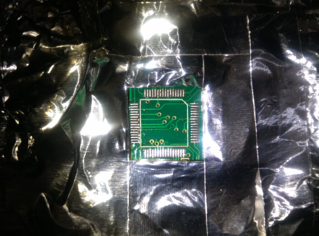
Take a picture of the lifted pad you have, it may still be possible to remove the mcu, clean things up and start over. I've done it before, just need a bit of care, and it depends on the current damage. If not, what Arakon suggested is correct, just remember to add a good amount of flux and DONOT drag the wick across the pins, and DONOT pull it hard if it adheres to the pins.
Here's the pic to see what's under the mcu:
Take a picture of the lifted pad you have, it may still be possible to remove the mcu, clean things up and start over. I've done it before, just need a bit of care, and it depends on the current damage. If not, what Arakon suggested is correct, just remember to add a good amount of flux and DONOT drag the wick across the pins, and DONOT pull it hard if it adheres to the pins.
Last edit: 30 Apr 2016 13:21 by silpstream.
- HappyHarry
-
- Offline
Less
More
- Posts: 1136
30 Apr 2016 13:29 #47486
by HappyHarry
Replied by HappyHarry on topic Ultimate7e tutorial: Processor upgrade
ok I've just pulled the mcu and what I was seeing was the white mcu outline not bridges, I have another 3 mcu's here so I'm away to start fresh with a new one just in case I buggered the chip somehow. I've managed to reposition the pulled trace without snapping it so I'm lucky there, fingers crossed this works!
- HappyHarry
-
- Offline
Less
More
- Posts: 1136
30 Apr 2016 15:26 - 30 Apr 2016 15:27 #47494
by HappyHarry
Replied by HappyHarry on topic Ultimate7e tutorial: Processor upgrade
"she's dead jim"
replaced the mcu with another and this one won't even connect to the stm, the soldering is prefect, there is no bridges but when i plug into the stlink it unloads from windows lol. i've obviously killed something else on the board. i even put back on the original 7e mcu and no difference. and when pulling that back off i managed to pull off a trace properly though it looks like it doesn't connect anyway (pin14 PA0-WKUP)
so be warned people this isn't an easy swap, i class myself as a competent solderer, and i've had 2 extra modules, 2 x 3way switches and the range mod under my belt on this tx, and i have the correct equipment for the job but i've still managed to kill my poor little 7e! so be careful if you plan to try this
Last edit: 30 Apr 2016 15:27 by HappyHarry.
- PhracturedBlue
-
- Offline
Less
More
- Posts: 4403
30 Apr 2016 15:48 #47495
by PhracturedBlue
Replied by PhracturedBlue on topic Ultimate7e tutorial: Processor upgrade
I think you were a bit too eager. It is very likely we could have found the issue with your tx had you left the 1st chip installed. If the stlink is working, you are very nearly there. At this point I don't know what to tell you. Once you start lifting traces, the task becomes much harder.
But having said that, I think we've said several times this is not for the feint of heart.
But having said that, I think we've said several times this is not for the feint of heart.
Time to create page: 1.322 seconds