
- Posts: 1971
Mjx Bugs 3
- hexfet
-
- Offline
Less
More
23 Mar 2018 23:15 #68317
by hexfet
Replied by hexfet on topic Mjx Bugs 3
Need some more spi captures from transmitters if you can do that. Blade81 ordered mentioned ordering a logic analyzer. I've ordered a receiver which may help if the A1 and A2 protocols are the same, but otherwise we need some captures from an A2 transmitter.
- C0ckpitvue 777
-
Topic Author
- Offline
Less
More
- Posts: 409
25 Mar 2018 03:06 #68336
by C0ckpitvue 777
Replied by C0ckpitvue 777 on topic Mjx Bugs 3
Does anyone has the 2nd version that can take captures,if so I will order the analyzer if you got a little soldering knowledge.Hexfet is realy trying to get this done,lets give him all the help he needs.
- Blade81
-
- Offline
Less
More
- Posts: 58
25 Mar 2018 04:44 #68339
by Blade81
Replied by Blade81 on topic Mjx Bugs 3
I got my logic analyser but i dont have a multi meter yet
- Blade81
-
- Offline
Less
More
- Posts: 58
27 Mar 2018 14:15 - 27 Mar 2018 14:17 #68372
by Blade81
Replied by Blade81 on topic Mjx Bugs 3
i got my multimeter and logic analyser, but im not sure where to start identifying the gnd.
Can anyone assist?
Can anyone assist?
Last edit: 27 Mar 2018 14:17 by Blade81.
- hexfet
-
- Offline
Less
More
- Posts: 1971
27 Mar 2018 15:35 #68373
by hexfet
Replied by hexfet on topic Mjx Bugs 3
Couldn't find a module online that looks like that one (8 pins). Just going by the trace sizes it's likely the two pins on the left are Vdd and ground. Check connectivity to black wire at the pad labeled GND. When trying to find signals this way keep in mind there may be a current path through the device which can read as a somewhat low resistance. Direct connect paths should read 0 ohms even when the test probe positions are swapped.
The three pins towards the other end may be the signals of interest (clock, chip select, and data). Can you get a picture of the other side of the board to check for connections there?
The three pins towards the other end may be the signals of interest (clock, chip select, and data). Can you get a picture of the other side of the board to check for connections there?
- Blade81
-
- Offline
Less
More
- Posts: 58
27 Mar 2018 21:51 #68374
by Blade81
Replied by Blade81 on topic Mjx Bugs 3
I will test every point if i have too but i need some time to complete
- Blade81
-
- Offline
Less
More
- Posts: 58
28 Mar 2018 01:47 - 28 Mar 2018 01:52 #68377
by Blade81
 I did the following, can you guys verify where I should solder them?
appreciated but electrical is not my thing so im pretty confuse as what is what
Replied by Blade81 on topic Mjx Bugs 3
appreciated but electrical is not my thing so im pretty confuse as what is what
Last edit: 28 Mar 2018 01:52 by Blade81.
- hexfet
-
- Offline
Less
More
- Posts: 1971
28 Mar 2018 01:55 - 28 Mar 2018 01:56 #68378
by hexfet
Replied by hexfet on topic Mjx Bugs 3
What are the numbers in your annotated picture? Not sure how to ask this politely - what is your general level of electronics knowledge? I'd like to give appropriate level instructions ")
If the annotations are resistance readings to the GND black wire, it looks like pin 2 (with 1 being leftmost in picture) is a likely candidate for ground. Next step would be to turn on power to the stock tx, then measure the voltage from GND to pin 1 and pin 2 (should be about 3..3 and 0 respectively).
If that's correct, connect logic analyzer ground to pin 2, and test probe lines to pins 3 through 8. Then make a capture, triggering starting on line 3 and bumping up until the trigger fires.
Edit: The only signals that matter are the ones on the radio module.
Last edit: 28 Mar 2018 01:56 by hexfet.
- ajtank
-
- Offline
Less
More
- Posts: 278
28 Mar 2018 02:09 #68379
by ajtank
Replied by ajtank on topic Mjx Bugs 3
It will help if you can remove the shield can. It is loosely soldered on the board and should not be difficult to remove.
- Blade81
-
- Offline
Less
More
- Posts: 58
28 Mar 2018 03:14 #68380
by Blade81
I work in IT, but am an idiot in electrical
I understand the concept of intercepting the data packet that flows in and out of the tx, is to first identify which channel is sending what data packet.
First is to identify the channels by its pin layout, the standard channels runs at a standard operating voltage, more or less.
so by running continuity, from the ground, is to identifying the (nearest) ground pad to get accurate reading when performing the voltage readings from the individual pads.
Perform voltage reading, identify the channels based on voltage readers, soldering the pins, connecting to the correct ports on the spi analyser, running the program to capture those data for "decoding" or "reverse engineering"
I happen to have few good electrical technician friends/colleagues in the company I work in so I borrowed their dmm and ask them how to use it.
But their DMM apparently is those expensive professional type and has too many options.
on top of it, I have no idea how to operate the multimeter but they guide me how to do that exactly base on serbydocky's video in the how to capture spi guide without having me drown in the pool of electrical knowledge lol
if u ask me what is dc what is ac, what is ohm, I rather you kill me LOL
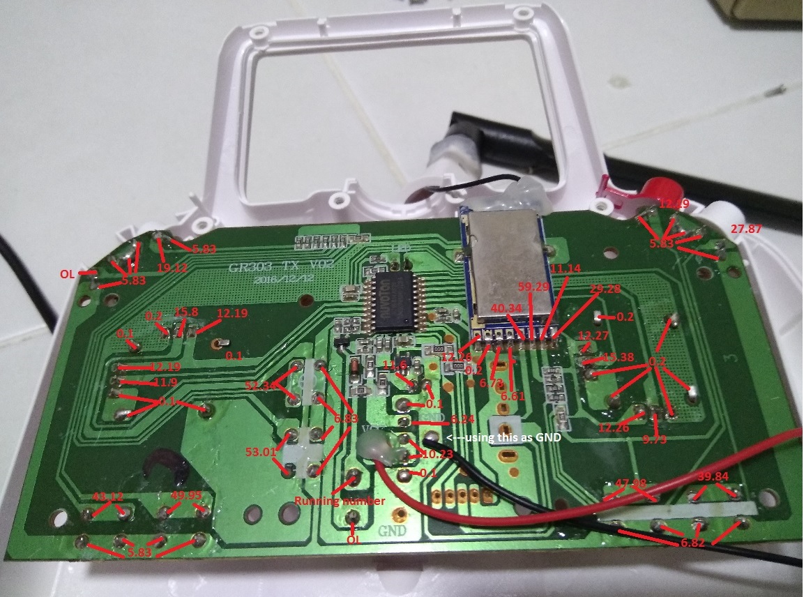
so The numbers in the first picture are resistance readings, with the DMM in continuity mode.
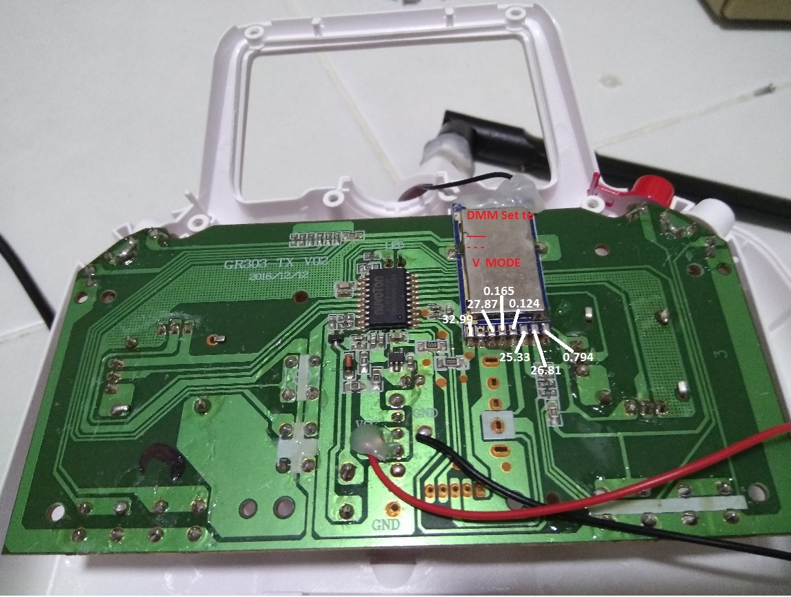
the 2nd picture is DMM in DC mode, checking the voltage readings of the pins, using the 2nd pad as ground. but I misread some of their decimal points.
which I was laughed at by my colleague when I told him my bugs 3 controller has a pad running 33v. he is like, bro you tx only uses 4 AA batteries, it cant be 33v LOL
I got my colleague to check and we went through with a 2nd reading. below is the updated readings.
Now I just need to know which pin to solder and plug to which channel on the spi analyser and I should be able to perform the capture.
sorry for being such a pain here and thank you for your patience and guide
Replied by Blade81 on topic Mjx Bugs 3
hexfet wrote: What are the numbers in your annotated picture? Not sure how to ask this politely - what is your general level of electronics knowledge? I'd like to give appropriate level instructions
If the annotations are resistance readings to the GND black wire, it looks like pin 2 (with 1 being leftmost in picture) is a likely candidate for ground. Next step would be to turn on power to the stock tx, then measure the voltage from GND to pin 1 and pin 2 (should be about 3..3 and 0 respectively).
If that's correct, connect logic analyzer ground to pin 2, and test probe lines to pins 3 through 8. Then make a capture, triggering starting on line 3 and bumping up until the trigger fires.
Edit: The only signals that matter are the ones on the radio module.
I work in IT, but am an idiot in electrical
I understand the concept of intercepting the data packet that flows in and out of the tx, is to first identify which channel is sending what data packet.
First is to identify the channels by its pin layout, the standard channels runs at a standard operating voltage, more or less.
so by running continuity, from the ground, is to identifying the (nearest) ground pad to get accurate reading when performing the voltage readings from the individual pads.
Perform voltage reading, identify the channels based on voltage readers, soldering the pins, connecting to the correct ports on the spi analyser, running the program to capture those data for "decoding" or "reverse engineering"
I happen to have few good electrical technician friends/colleagues in the company I work in so I borrowed their dmm and ask them how to use it.
But their DMM apparently is those expensive professional type and has too many options.
on top of it, I have no idea how to operate the multimeter but they guide me how to do that exactly base on serbydocky's video in the how to capture spi guide without having me drown in the pool of electrical knowledge lol
if u ask me what is dc what is ac, what is ohm, I rather you kill me LOL
so The numbers in the first picture are resistance readings, with the DMM in continuity mode.
the 2nd picture is DMM in DC mode, checking the voltage readings of the pins, using the 2nd pad as ground. but I misread some of their decimal points.
which I was laughed at by my colleague when I told him my bugs 3 controller has a pad running 33v. he is like, bro you tx only uses 4 AA batteries, it cant be 33v LOL
I got my colleague to check and we went through with a 2nd reading. below is the updated readings.
Now I just need to know which pin to solder and plug to which channel on the spi analyser and I should be able to perform the capture.
sorry for being such a pain here and thank you for your patience and guide
- hexfet
-
- Offline
Less
More
- Posts: 1971
28 Mar 2018 12:16 - 28 Mar 2018 12:18 #68387
by hexfet
Replied by hexfet on topic Mjx Bugs 3
Not a problem, thanks for doing the work. It does look like the first pin is power and the second pin is ground. It's difficult to tell with a voltmeter what the other pins are, so the easiest way forward is to hook them all up to the logic analyzer. Doesn't matter which pin to which channel, though probably easier to talk about if you keep them in order. Set the logic analyzer to edge trigger on any one of them, and if it doesn't trigger then try the next one till a trigger occurs. Make a capture file of what happens when the tx is powered on and we can start from there.
Last edit: 28 Mar 2018 12:18 by hexfet.
- Blade81
-
- Offline
Less
More
- Posts: 58
28 Mar 2018 15:25 #68391
by Blade81
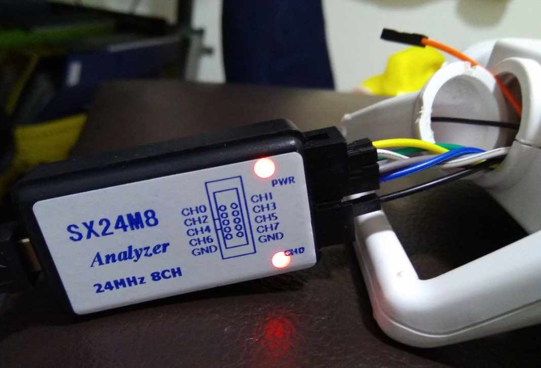
like to check, the 3.3v from the pin, does it needs to be connected to the spi analyzer? i left it unplugged fearing it may short something if i plug in wrongly.
also, i did a test capture. if it looks alright i will continue to capture the entire BIND, ARM, DISARM sequence
Replied by Blade81 on topic Mjx Bugs 3
like to check, the 3.3v from the pin, does it needs to be connected to the spi analyzer? i left it unplugged fearing it may short something if i plug in wrongly.
also, i did a test capture. if it looks alright i will continue to capture the entire BIND, ARM, DISARM sequence
- hexfet
-
- Offline
Less
More
- Posts: 1971
28 Mar 2018 16:24 #68393
by hexfet
Replied by hexfet on topic Mjx Bugs 3
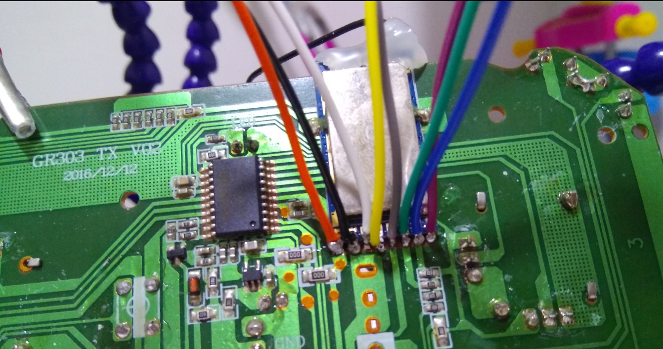
Looks good! The power pin does not need to be connected to the analyzer. Please configure the SPI analyzer with Enable on channel 0, Clock on 1, MOSI on 2, and MISO none. Set the display radix to hex. Then save the captures by exporting to csv format. Don't need the raw files.
- Blade81
-
- Offline
Less
More
- Posts: 58
28 Mar 2018 21:33 #68395
by Blade81
Replied by Blade81 on topic Mjx Bugs 3
I did a couple of captures,I hope that helps.
let me know if there is anything else i can help
Thank you!!
let me know if there is anything else i can help
Thank you!!
- hexfet
-
- Offline
Less
More
- Posts: 1971
29 Mar 2018 03:18 #68396
by hexfet
Replied by hexfet on topic Mjx Bugs 3
Test build
is updated (f8892d4). Have only gone through the initialization and bind information so far. The A2 protocol is different from the A1 captures from C0ckpitvue. The biggest difference is 16 hopping frequencies instead of 7. The bind information is also slightly changed. Best to test with props removed. Check if you can bind to the quad with this build. If successful check if it arms when channel 5 is set to a value greater than 0.
Unless someone has an A1 version to test with I don't intend to continue trying to implement that variation. When I ordered the A2 receiver the A1 was shown as an option but selecting it changed the status to "no longer available".
Unless someone has an A1 version to test with I don't intend to continue trying to implement that variation. When I ordered the A2 receiver the A1 was shown as an option but selecting it changed the status to "no longer available".
- davdrone1
-
- Offline
- davdrone1
Less
More
- Posts: 91
29 Mar 2018 04:02 #68397
by davdrone1
Time flies like a banana
Replied by davdrone1 on topic Mjx Bugs 3
Tried the updated build (f8892d4) on my two Bugs 3s. Both have A2 boards.
Unable to bind either model. No sign of any communication.
Unable to bind either model. No sign of any communication.
Time flies like a banana
- Blade81
-
- Offline
Less
More
- Posts: 58
29 Mar 2018 04:45 - 29 Mar 2018 04:49 #68399
by Blade81
Replied by Blade81 on topic Mjx Bugs 3
same behavior as previously, select "bind" on t8sg, power on quad, drone flashing lights go steady in number of seconds. unable to arm. channel 5 was map to SW-D.
Btw, i must mention that bug3 original TX has few features that could prohibit us to arm too.
example, does not arm Unless throttle stick is all the way down.
disarm requires long press of the red button,
continuous short Beeps when it goes low RSSI
continuous short Beeps when quad is turn off while tx is still on
continuous long beeps when battery is low
the red button, is used for binding, arming, disarming.
bind sequence requires this red button to be hold down while powering up
Last edit: 29 Mar 2018 04:49 by Blade81.
- davdrone1
-
- Offline
- davdrone1
Less
More
- Posts: 91
29 Mar 2018 05:32 #68401
by davdrone1
Time flies like a banana
Replied by davdrone1 on topic Mjx Bugs 3
When I tried the latest test build running on my Jumper with both of my Bugs 3s, I didn't try the "Freq Tune" option, to step thru the range from -300 to +300.
Should I try to do this, to improve the chances of a bind?
Should I try to do this, to improve the chances of a bind?
Time flies like a banana
- hexfet
-
- Offline
Less
More
- Posts: 1971
29 Mar 2018 12:20 #68403
by hexfet
Replied by hexfet on topic Mjx Bugs 3
Thanks for the testing. I'll go through all the captures this weekend to see if I spot anything. At this point, without a capture from the rx, there's no way to tell if there's something wrong with the protocol transmit code, or the rx is receiving but something's wrong in the data, or the rx is responding but the tx isn't getting the packets. According to package tracking my receiver has not yet arrived in the US.
The frequency tuning is worth a try. I haven't needed it with my hubsan or V911.
The frequency tuning is worth a try. I haven't needed it with my hubsan or V911.
- hexfet
-
- Offline
Less
More
- Posts: 1971
30 Mar 2018 02:23 #68415
by hexfet
Replied by hexfet on topic Mjx Bugs 3
New
test build
(e15ee22) available. Changed the way the check for data from the rx is made. Don't think the a7105 works the way I thought in this area - the documentation is not too clear. Can't use the exact same method as the stock tx because it uses a GIO pin to check status.
Time to create page: 0.364 seconds
-
Home

-
Forum
-
Development
-
Protocol Development
- Mjx Bugs 3