
- Posts: 304
Deviation for Devo F4?
- Arnold
-
- Offline
Less
More
14 May 2016 02:23 #48396
by Arnold
Too many hobbies & too many Devos!
Who knows where the time goes?
Replied by Arnold on topic Deviation for Devo F4?
Thank you.
Too many hobbies & too many Devos!
Who knows where the time goes?
Please Log in or Create an account to join the conversation.
- Epitaph
-
Topic Author
- Offline
Less
More
- Posts: 291
20 May 2016 02:41 #48798
by Epitaph
Replied by Epitaph on topic Deviation for Devo F4?
Hi guys
I'm going to be doing a little test, specifically with the FMODE connection on the transmitter. The pin is indicated on the diagram that was posted a while back, just not actually connected to anything. I'm going to start off opening up my 7E to see if the FMODE switch just grounds this pin which I imagine is what it does.
The thing is, I wanted to know if the software is "ready" for FMODE to use the pin assigned on the diagram (assuming the diagram is correct, which many of the others are), or if it would need to be activated or rerouted or something in the deviation software for it to work.
Please Log in or Create an account to join the conversation.
- Epitaph
-
- Offline
Less
More
- Posts: 291
20 May 2016 03:02 #48816
by Epitaph
Replied by Epitaph on topic Deviation for Devo F4?
Right, I've just opened up my 7E and tried it out with the multimeter, and both the THOLD and the FMODE switches just ground the corresponding pin directly. The black wire on each switch goes to ground, and the red goes to the main board direct to a pin as follows
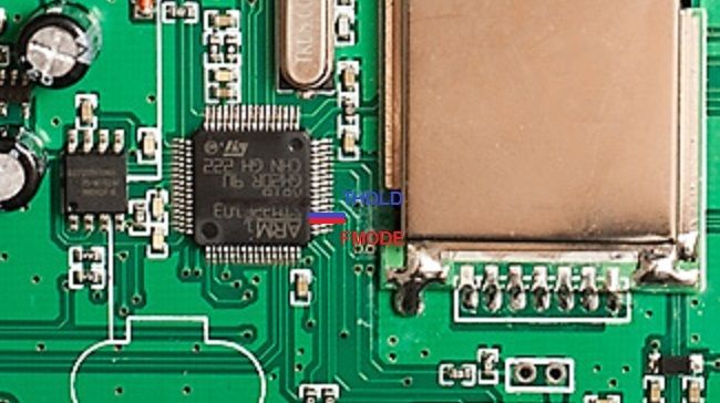
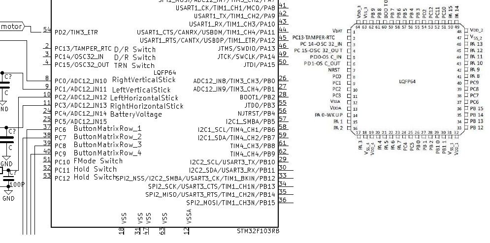
The red is the FMODE switch, which is the 3rd pin from the botton, and blue is THOLD which is the 4th pin from the bottom. According to the diagram of the F4, they happen to be the same pins so seeing as the F4 firmware is already based on existing firmwares, I'm going to try it out and see if I can get these 2 switches to activate.
The red is the FMODE switch, which is the 3rd pin from the botton, and blue is THOLD which is the 4th pin from the bottom. According to the diagram of the F4, they happen to be the same pins so seeing as the F4 firmware is already based on existing firmwares, I'm going to try it out and see if I can get these 2 switches to activate.
Please Log in or Create an account to join the conversation.
- Epitaph
-
- Offline
Less
More
- Posts: 291
20 May 2016 04:19 #48835
by Epitaph
Replied by Epitaph on topic Deviation for Devo F4?
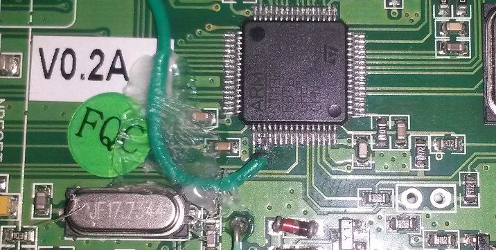
So, guys, I have news... I have soldered the switch to the corresponding pin on the F4 for the FMODE switch, AND IT WORKS!!!
It's really hard to solder, and especially considering that it seems the THOLD switch is right next to it (hence why I haven't added it yet)but it is possible if you take your time. I tried it out by setting it up for 50% rates, and I could see in the channel monitor how the rates were changing from 100% to 50% as I flicked the switch!!
I'll try with the THOLD switch later on, but it's such a strain on my eyes and hand I need a quick break first... but I'm hopeful it works too.
As I said, just connect this to the centre of the 2 way switch, and the top pin of the switch to ground, which you have the gimbal grounds right next to the switches to pick up from no problem.
Please Log in or Create an account to join the conversation.
- Epitaph
-
- Offline
Less
More
- Posts: 291
20 May 2016 05:22 - 20 May 2016 06:29 #48838
by Epitaph
Replied by Epitaph on topic Deviation for Devo F4?
Right, small update...
I haven't been able to figure out THOLD on the transmitter... and seeing as I only use it as literally a throttle cut always, I'll probably just wire it in as such electronically (changing the signal pin on the throttle channel from the centre pin of the pot to the throttle minimum).
The other thing, the FMODE switch only half works... I tried by setting up dual rates, using FMODE1 as the trigger, and it works great (and in the way I like it, down for high rates, up for low). BUT, if you set it up as FMODE0, it doesn't do anything. It seems that the switch activates only the on/off status of FMODE1, but doesn't affect FMODE0 at all, so it doesn't change between them.
I don't know if this is a hardware or a software issue, if it can be fixed or even if it's worth fixing (not sure how many will do the soldering, it's pretty hard to do), but just bare that in mind. I tried to see if this was the case for HOLD, but it's not as it did nothing at all independently on if it was set as HOLD0 or HOLD1
EDIT:
I didn't realise there was an FMODE2 option, I thought it was an FMODE0 and 1, and nothing more... anyway, my switch changes between FMODE 1 and 2... maybe it would work 0, 1 and 2 if I used a 3 position switch, maybe going from GND to Vcc, or unless it's 2 pins on the MCU... in any case, if someone else wants to experiment with it, the pins do seem to be there, it's just a case of finding them. Supposedly, there is a GEAR switch, a D/R switch, a MIX switch... which might be worth looking into to see if any of them can be found... I might try looking for them later on, as it would be interesting if I could wire the pot I added directly into the transmitter without having to use an Arduino to control it... for the time being, I have an FMODE switch working, as well as a HOLD switch adapted, just not via software
(If anyone wants to add a throttle hold switch direct without software, as in purely a throttle hold switch that puts in -100 value, it's pretty easy. Add a 2 position switch to the transmitter, and then remove the yellow signal wire from the throttle pot and solder it to the central pin of the new switch. Then solder a wire from the top pin of the switch to ground, and the bottom pin of the switch to the central pin of the pot (where the yellow wire used to be). This way, when the case is closed up and ready to use, with the switch up, the throttle acts normal, but with the switch down, the signal is directed into the throttle minimum directly without going through the pot, giving the minimum value constant, no matter where the throttle is. Returning the switch back to the up position with put the throttle in working again, and it will register in the position it's in at that moment.)
Last edit: 20 May 2016 06:29 by Epitaph.
Please Log in or Create an account to join the conversation.
- SirDomsen
-
- Offline
20 May 2016 08:43 #48849
by SirDomsen
Replied by SirDomsen on topic Deviation for Devo F4?
Interesting stuff. did you wire it according to F7?
Another question: I have issues with my F4 using Deviation. Sometimes Mixer Values disappear - or change without any warning. Sometimes everything works fine, then i swotch off an d on the TX - some parts of the model file are missing - e.g. mixers or switches. Can you confirm that?
Second strange thing: sometimes if I power my F4 up, the screen remains blue without any signs on it, mostly while the TX was not powered on for a longer time. Video is switched off - no OSD. Other functions still work, it is able to bind, you even can fly without issues - but menu is not accessable. Sometimes I have to enter flash Mode/USB mode to reactivate the menu, sometimes it's enough just zo power off and on again. Can you confirm such a behavior, too?
Please Log in or Create an account to join the conversation.
- Epitaph
-
- Offline
Less
More
- Posts: 291
20 May 2016 15:16 #48871
by Epitaph
Replied by Epitaph on topic Deviation for Devo F4?
I don't seem to have any of those issues that you describe, but also I haven't been able to fly much lately for various reasons, and most of what I know as to issues is during tests at home... as I said, no issues thus so far apart from the text remaining on screen until overwritten by something else and the channel monitor having values off screen... but then again I'm still with v4.0.1-aa82a64 at the moment.
I couldn't base myself off the F7 because I don't have one to find the pins of anything on... what I did was base myself off my 7E, and with that "guessed" the orientation of the chipset, that and the fact that I followed the TCK pad back to the pin on the MCU and that coincided.
I think I can't base myself really off the 7E, as I didn't realise the F7 has a 3 position switch for FMODE... the question would be what does the switch commute between, as there is only one pin on the MCU for that function... could it be between GND and Vcc?? I'm not brave enough really to start pumping voltage into that pin just to find out, maybe someone with an F7 can test the 3 pins on the FMODE switch they have to see what that 3rd pin connects to. I would also be interested in knowing which pin AUX2 goes to on the MCU, although I suspect it's going through a resistor, for the same reason I'm not going to put Vcc straight into the MCU... the 4 stick axis have that type of setup, and a resistor in series (as well as a capacitor to GND), so they must be there for a reason!!
It's a shame I couldn't figure out the HOLD switch, it would have been nice if it were programmable, but not essential I guess... in the mean time, my diodes arrived today so I can wire up switches A and B as you already figured out, and that will be all the switches I've added (2 three-way and 2 two-way) connected somehow or other, and just the pot left for connecting.
I may try and figure out MIX as that's marked up on the diagram, with pins for MIX0 and MIX2, which is a 3 way switch on the F7... I have a feeling it might be those 2 pins on the outside pins of the switch, and the middle going to GND. D/R and GEAR are also on the diagram which are just simple 2 way switches each, and one pin each, so that's probably just one switch pin to the MCU, and one to GND, the 3rd switch pin not connected... if one of those is figured out, it can be used as an independent switch or as a substitute HOLD, or maybe as a dedicated video switch so we can leave the TRIM to be a TRIM (I don't know how to change that switch assignment in the model, I've tried it with the FMODE switch and it didn't work, maybe you can figure that one out?)... but right now, with you figuring out the A and B switches, we already have a nice number of controls on the transmitter!!
Please Log in or Create an account to join the conversation.
- Epitaph
-
- Offline
Less
More
- Posts: 291
20 May 2016 15:30 - 20 May 2016 15:32 #48873
by Epitaph
Replied by Epitaph on topic Deviation for Devo F4?
Also Sir, I have a question for you... back on page 13 you took a couple of photos for the A and B switches... there are 2 pins I can't make out for sure, and wanted to know if you could verify it.
In the 3 pins where the red and black wires are soldered on the main board, is the black soldered to the top pin, and the red to the bottom, leaving the middle pin free??
Also, did you have to change the hardware file in the DEVOFS for them to work or were they already activated?
In the 3 pins where the red and black wires are soldered on the main board, is the black soldered to the top pin, and the red to the bottom, leaving the middle pin free??
Also, did you have to change the hardware file in the DEVOFS for them to work or were they already activated?
Last edit: 20 May 2016 15:32 by Epitaph.
Please Log in or Create an account to join the conversation.
- Arnold
-
- Offline
Less
More
- Posts: 304
20 May 2016 19:33 #48889
by Arnold
You can fly with the F4? I can't because I can't turn - AIL and RUD do not work. You mentioned this in post #46213 in early April. Did I miss something somewhere? I tried a nightly from a few days ago, but still not working.
I'm not seeing any of the other issues you mention here, but I don't have any FPV capability yet - waiting for parts..
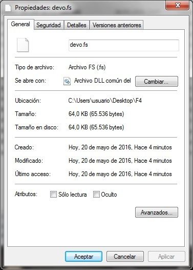
** Am I the only one here that cannot make a demo.fs file under 65,536 bytes? (On Mac, Linux, and Raspberry Pi so far....) I tried one yesterday where buildfs reported the result was 24K, but the operating system saw it as 66K. I don't know what's wrong. Must I be using Windows to do this?
Epitaph, nice work on the switches. I've ordered some switches, but haven't looked carefully at what it will take to install them. You can be my guide
Too many hobbies & too many Devos!
Who knows where the time goes?
Replied by Arnold on topic Deviation for Devo F4?
SirDomsen wrote: Interesting stuff. did you wire it according to F7?
Another question: I have issues with my F4 using Deviation. Sometimes Mixer Values disappear - or change without any warning. Sometimes everything works fine, then i swotch off an d on the TX - some parts of the model file are missing - e.g. mixers or switches. Can you confirm that?
Second strange thing: sometimes if I power my F4 up, the screen remains blue without any signs on it, mostly while the TX was not powered on for a longer time. Video is switched off - no OSD. Other functions still work, it is able to bind, you even can fly without issues - but menu is not accessable. Sometimes I have to enter flash Mode/USB mode to reactivate the menu, sometimes it's enough just zo power off and on again. Can you confirm such a behavior, too?
You can fly with the F4? I can't because I can't turn - AIL and RUD do not work. You mentioned this in post #46213 in early April. Did I miss something somewhere? I tried a nightly from a few days ago, but still not working.
I'm not seeing any of the other issues you mention here, but I don't have any FPV capability yet - waiting for parts..
** Am I the only one here that cannot make a demo.fs file under 65,536 bytes? (On Mac, Linux, and Raspberry Pi so far....) I tried one yesterday where buildfs reported the result was 24K, but the operating system saw it as 66K. I don't know what's wrong. Must I be using Windows to do this?
Epitaph, nice work on the switches. I've ordered some switches, but haven't looked carefully at what it will take to install them. You can be my guide
Too many hobbies & too many Devos!
Who knows where the time goes?
Please Log in or Create an account to join the conversation.
- Epitaph
-
- Offline
Less
More
- Posts: 291
20 May 2016 19:50 - 20 May 2016 20:16 #48891
by Epitaph
Replied by Epitaph on topic Deviation for Devo F4?
I've written it in Windows, but one thing I have done is rather than writing it on the computer and then copying it to the transmitter, I've written it direct to the transmitter plugged in as if I was writing direct to a USB drive, and it worked fine.
One thing I find a little strange also is the size, as you say it's 66kb, yet mine come up as 64kb. I don't know if it's how the file is being written or if it's the different computer's interpretation of the file size... How about I send you my FS file and you see if you can copy it onto your transmitter?? It's just a basic from scratch setup with no added models or anything, the only thing I have done is add DSMX to the list of protocols (which makes 3 in total now), and I added the virtual channel to every model so that the video is controlled by the trim tab on every model from scratch before setting it up. Bare in mind that this is from the version of Deviation I have installed, I don't know if it would work or not, but it's worth a try I guess to at least see if you can rule out where the problem is (file being written too large, computer not accepting the size for the drive, etc.)
EDIT:
Sorry, my Model 1 is slightly changed, as it has FMODE assigned to channel 5 for tests, but that you can just remove. Forgot I had it assigned...
Last edit: 20 May 2016 20:16 by Epitaph.
Please Log in or Create an account to join the conversation.
- Epitaph
-
- Offline
Less
More
- Posts: 291
20 May 2016 20:04 - 20 May 2016 20:23 #48893
by Epitaph
Replied by Epitaph on topic Deviation for Devo F4?
As far as the switches go, if you want to add the A and B switches, you need the switches and some diodes (1N4148 for example). The switches can be either 2 position or 3 position, but they only have to be single pole.
For the FMODE switch I added, it's just a single 2-way switch and 2 wires connected, only one of the wires if very hard to solder into place because you can bridge several pins ont he MCU if not careful... best way is to cut the strands of the wore down to leave just a couple of strands, tin them finely, then with the soldering iron clean (no solder on the tip), just position the wire into place and apply the heat to the wire, and the tinning of the strands should take to the pin. This is very easy to break off if the wire is allowed to move, so just use a dab of hot glue to glue the wire into position close to the solder point (but not on it, in case you need to access those solder points later), and that should stop any movement getting to the solder point. FMODE doesn't need any configuring in the FS file to work, it's already in there... and it works between FMODE1 and FMODE 2... it turns out the Devo F7 FMODE switch is a 3 way one, and I didn't know this, I was basing off the 7E one which is only 2 way... problem is I haven't figured out which is the way to get FMODE0 working... but with FMODE1 and 2 working, you have the equivalent of the 7E version of FMODE, which is a basic 2 position switch and it works perfectly both for toggling mixes of dual rates, as it does for controlling a channel. The solder point on the MCU is the 3rd pin from the left on the bottom side of the MCU, and ONLY the 3rd pin, try not to bridge it to any other adjacent pins.
The other end of the green wire goes to the centre pin on the 2-way switch. The top pin of the 2-way switch just goes straight to ground, which you can connect it for example to the black wire on the elevator pot if you want as it's right next to the switch (where I installed it anyway). The bottom pin of the 2-way switch isn't connected to anything.
The HOLD switch is again, just a basic 2-way switch, but I don't have it working through software, so it's not assignable... it is PURELY a throttle cut switch and nothing else. This is easy to do and the solder points are easy too. Just unsolder the yellow (centre) wire on the throttle pot and extend the wire to reach to where the switch is going. Then solder this wire to the centre pin of the 2-way switch. Next, solder a wire from the top pin of the 2-way switch to the bottom pin on the throttle pot, which already has a black wire on it (this will leave the pin with 2 wires soldered on it, it's adding a wire, not replacing it). Then finally just solder a wire from the bottom pin on the 2-way switch to the centre pin on the pot where the yellow throttle wire was originally before you removed it. When the switch is up, the throttle stick works as normal. When the switch is down, then it is fixed in the -100 position (minimum throttle). You can change the throttle stick position no problem, when you flick the switch back up, it will go back to normal throttle operation on the position you have it in at that time, just like the programmable HOLD switch on other transmitters.
I'll take some photos of the HOLD switch wiring next time I open the transmitter, or I'll just draw a diagram or something")
For the FMODE switch I added, it's just a single 2-way switch and 2 wires connected, only one of the wires if very hard to solder into place because you can bridge several pins ont he MCU if not careful... best way is to cut the strands of the wore down to leave just a couple of strands, tin them finely, then with the soldering iron clean (no solder on the tip), just position the wire into place and apply the heat to the wire, and the tinning of the strands should take to the pin. This is very easy to break off if the wire is allowed to move, so just use a dab of hot glue to glue the wire into position close to the solder point (but not on it, in case you need to access those solder points later), and that should stop any movement getting to the solder point. FMODE doesn't need any configuring in the FS file to work, it's already in there... and it works between FMODE1 and FMODE 2... it turns out the Devo F7 FMODE switch is a 3 way one, and I didn't know this, I was basing off the 7E one which is only 2 way... problem is I haven't figured out which is the way to get FMODE0 working... but with FMODE1 and 2 working, you have the equivalent of the 7E version of FMODE, which is a basic 2 position switch and it works perfectly both for toggling mixes of dual rates, as it does for controlling a channel. The solder point on the MCU is the 3rd pin from the left on the bottom side of the MCU, and ONLY the 3rd pin, try not to bridge it to any other adjacent pins.
The other end of the green wire goes to the centre pin on the 2-way switch. The top pin of the 2-way switch just goes straight to ground, which you can connect it for example to the black wire on the elevator pot if you want as it's right next to the switch (where I installed it anyway). The bottom pin of the 2-way switch isn't connected to anything.
The HOLD switch is again, just a basic 2-way switch, but I don't have it working through software, so it's not assignable... it is PURELY a throttle cut switch and nothing else. This is easy to do and the solder points are easy too. Just unsolder the yellow (centre) wire on the throttle pot and extend the wire to reach to where the switch is going. Then solder this wire to the centre pin of the 2-way switch. Next, solder a wire from the top pin of the 2-way switch to the bottom pin on the throttle pot, which already has a black wire on it (this will leave the pin with 2 wires soldered on it, it's adding a wire, not replacing it). Then finally just solder a wire from the bottom pin on the 2-way switch to the centre pin on the pot where the yellow throttle wire was originally before you removed it. When the switch is up, the throttle stick works as normal. When the switch is down, then it is fixed in the -100 position (minimum throttle). You can change the throttle stick position no problem, when you flick the switch back up, it will go back to normal throttle operation on the position you have it in at that time, just like the programmable HOLD switch on other transmitters.
I'll take some photos of the HOLD switch wiring next time I open the transmitter, or I'll just draw a diagram or something
Last edit: 20 May 2016 20:23 by Epitaph.
Please Log in or Create an account to join the conversation.
- SirDomsen
-
- Offline
20 May 2016 21:33 #48903
by SirDomsen
Replied by SirDomsen on topic Deviation for Devo F4?
@ Epitaph. did you use
this
? Maybe very helpful for your switch mod.
For my 2x 3way mod I'll do some new pictures soon. Just had to open up the TX again for another reason...
For my 2x 3way mod I'll do some new pictures soon. Just had to open up the TX again for another reason...
Please Log in or Create an account to join the conversation.
- Epitaph
-
- Offline
Less
More
- Posts: 291
20 May 2016 21:43 - 20 May 2016 21:44 #48904
by Epitaph
Replied by Epitaph on topic Deviation for Devo F4?
No, I didn't use that, I used a PDF that was posted a while back which is a schematic but with basically the same information... because I wasn't sure how valid it was, I tried following traces on my 7e to see where things were connected. That also helped to figure out what side was what on the transmitter as to MCU orientation, as well as to verify that the switches indeed just ground the pin in question.
Last edit: 20 May 2016 21:44 by Epitaph.
Please Log in or Create an account to join the conversation.
- SirDomsen
-
- Offline
20 May 2016 21:57 #48906
by SirDomsen
Replied by SirDomsen on topic Deviation for Devo F4?
Pins are GNDed, right. I discussed with PhracturedBlue a while ago, but as he told me that the 7e remaining stuff will be likely cleaned out the F4, the Switches won't work anymore until you build your own Deviation version. So I decided to add more switches using an Arduino - works great indeed! The point where I got the 5V was not goog I think though - might cause my display/OSD failures. That's why i opende the TX again.
Btw: The F7 connections should be correct afaik, so no need to trace lines if you want to connect them the F7 way...
Btw: The F7 connections should be correct afaik, so no need to trace lines if you want to connect them the F7 way...
Please Log in or Create an account to join the conversation.
- SirDomsen
-
- Offline
20 May 2016 23:08 #48908
by SirDomsen
Damn, the pictures I just took are as nasty as the first ones, so not as useful as them, and at the moment I don't feel like opening up the TX again
To answer your questions:
1) Black wire goes to middle pin, red wire to the bottom
2)hardware.ini has to be changed as on 7E. Switches need to be commented in
Replied by SirDomsen on topic Deviation for Devo F4?
Epitaph wrote: Also Sir, I have a question for you... back on page 13 you took a couple of photos for the A and B switches... there are 2 pins I can't make out for sure, and wanted to know if you could verify it.
In the 3 pins where the red and black wires are soldered on the main board, is the black soldered to the top pin, and the red to the bottom, leaving the middle pin free??
Also, did you have to change the hardware file in the DEVOFS for them to work or were they already activated?
Damn, the pictures I just took are as nasty as the first ones, so not as useful as them, and at the moment I don't feel like opening up the TX again
To answer your questions:
1) Black wire goes to middle pin, red wire to the bottom
2)hardware.ini has to be changed as on 7E. Switches need to be commented in
Please Log in or Create an account to join the conversation.
- Arnold
-
- Offline
Less
More
- Posts: 304
20 May 2016 23:43 - 14 Jun 2016 04:49 #48909
by Arnold
Thanks, I'll try that since the way I'm doing it is driving me bananas - and I prefer apples
Too many hobbies & too many Devos!
Who knows where the time goes?
Replied by Arnold on topic Deviation for Devo F4?
Epitaph wrote: I've written it in Windows, but one thing I have done is rather than writing it on the computer and then copying it to the transmitter, I've written it direct to the transmitter plugged in as if I was writing direct to a USB drive, and it worked fine...
Thanks, I'll try that since the way I'm doing it is driving me bananas - and I prefer apples
Too many hobbies & too many Devos!
Who knows where the time goes?
Last edit: 14 Jun 2016 04:49 by Arnold.
Please Log in or Create an account to join the conversation.
- Epitaph
-
- Offline
Less
More
- Posts: 291
21 May 2016 00:50 #48910
by Epitaph
Replied by Epitaph on topic Deviation for Devo F4?
I know what you mean Sir... I only based off the 7E as into pin identification and "what it does" when it leaves the MCU, which it turns out is just going to the switch, which in turn sends it off to ground. Apart from that it's more based off the F7 really... I just don't have an F7 to confirm with a multimeter in these things.
The diagram I used is this one here:
Now, I'm not sure everythign is correct as the matrix for the A and B buttons was different to this according to PB, but at the same time, some things are the same, and you can see what's what on the diagram... the image of the pinouts on the top right hand corner is upside down, so just rotate it 180º to get which pins are which on the chipset according to the orientation it actually has in the transmitter.
What is a little confusing is the fact that the HOLD switch has 2 assigned pins on the MCU if you look, the 2 pins right next to the single FMODE one... now, I've tried both of them out for HOLD, and neither gave a result... I'm wondering if HOLD is achieved maybe by bridging the 2, which if that's the case, is a real hard solder to do and I'll just stick with the mod I made myself.
Another thing I'm not sure of is one of the HOLD pins, along with a few others are with an asterisk, and I'm not sure what that means, if that might be relevant. If you look, there is a MIX0 and a MIX2 pin on the diagram and they have an asterisk too, so I'm not sure if they are like "on the F7 but serve no purpose on the F4"... but then in that case, why is there no mention of the AUX2 knob from the F7?
I will be trying out the GEAR pin later on to see if that gives any results, because if we can find out some of these pins, even if you or I don't actually use them ourselves, someone might, because there are people that want to add a couple of switches, no knobs, and find Arduino's a little daunting because of having to code things, so it would be nice to have all those options... besides, if I can find a couple of switches to work like the FMODE one does, then that also gives options to people that want to add them WITH an Arduino, and have a $50 nuclear power plant in their hands hehehehe
As well as the GEAR switch, there is also the D/R switch to look into...
Please Log in or Create an account to join the conversation.
- Arnold
-
- Offline
Less
More
- Posts: 304
21 May 2016 05:11 #48934
by Arnold
You screenshot shows exactly the precise number of bytes (65536) as my system shows. The Mac must round the number upwards for the approx. size (66Kb). I'll give some attention to the ZIP file you provided when I have more time - soon, I hope.
Too many hobbies & too many Devos!
Who knows where the time goes?
Replied by Arnold on topic Deviation for Devo F4?
Epitaph wrote: ... One thing I find a little strange also is the size, as you say it's 66kb, yet mine come up as 64kb. I don't know if it's how the file is being written or if it's the different computer's interpretation of the file size... How about I send you my FS file and you see if you can copy it onto your transmitter?
You screenshot shows exactly the precise number of bytes (65536) as my system shows. The Mac must round the number upwards for the approx. size (66Kb). I'll give some attention to the ZIP file you provided when I have more time - soon, I hope.
Too many hobbies & too many Devos!
Who knows where the time goes?
Please Log in or Create an account to join the conversation.
- SirDomsen
-
- Offline
21 May 2016 06:29 - 21 May 2016 09:49 #48935
by SirDomsen
Replied by SirDomsen on topic Deviation for Devo F4?
I already did something like a nuclear Power Plant with my F4 
The diagram of the F4 internals has some mistakes iirc.
Try using the pinouts from the wiki section. The button matrix is correct there, otherwose the switchmod won't work.
A tipp for direct mcu wiring: I'm using old ATA133 cables to wire, the adders are really small and good to solder.
The diagram of the F4 internals has some mistakes iirc.
Try using the pinouts from the wiki section. The button matrix is correct there, otherwose the switchmod won't work.
A tipp for direct mcu wiring: I'm using old ATA133 cables to wire, the adders are really small and good to solder.
Last edit: 21 May 2016 09:49 by SirDomsen.
Please Log in or Create an account to join the conversation.
- Arnold
-
- Offline
Less
More
- Posts: 304
22 May 2016 22:12 #49051
by Arnold
Wow, you can be quite busy flipping all those switches and twiddling those knobs! Nice job.
I notice something on the top of your F4 different from my Tx. You have what looks like a plug on top next to the antenna. Did you add that?
Mine looks like this - no plug there::
www.dropbox.com/sc/vniu02dxz0sdhar/AACEi3pQ5hq8IxJBfFz2FuGIa
And the antenna mount has that extra passage way for an external module antenna = tempting me ...
Too many hobbies & too many Devos!
Who knows where the time goes?
Replied by Arnold on topic Deviation for Devo F4?
SirDomsen wrote: I already did something like a nuclear Power Plant with my F4 ...
Wow, you can be quite busy flipping all those switches and twiddling those knobs! Nice job.
I notice something on the top of your F4 different from my Tx. You have what looks like a plug on top next to the antenna. Did you add that?
Mine looks like this - no plug there::
www.dropbox.com/sc/vniu02dxz0sdhar/AACEi3pQ5hq8IxJBfFz2FuGIa
And the antenna mount has that extra passage way for an external module antenna = tempting me ...
Too many hobbies & too many Devos!
Who knows where the time goes?
Please Log in or Create an account to join the conversation.
Time to create page: 0.612 seconds
-
Home

-
Forum
-
Development
-
Development
- Deviation for Devo F4?